Common industry terms
- Home
- »
- LED Academy
- »
- Common LED Screen Industry Terms
Table of Contents
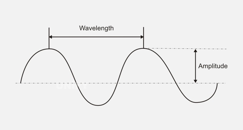
Wavelength
Wavelength refers to the distance a wave travels in one vibration cycle. The wavelength diagram is shown in Figure 1-9. The wavelength range of visible light is between 400 (purple light) and 700nm (red light). Generally, the wavelength range of red light is 620-680nm, the wavelength range of green light is 490-570nm, and the wavelength range of blue light is 420-490nm.
Pixels
Pixels refer to the light points composed of a single or multiple light-emitting tubes. They are the smallest unit on the screen that can be independently controlled. In English, they are expressed as Pixel. On a full-color LED display, pixels are composed of three parts: red, green, and blue. Each part is composed of one or several LEDs. Any color can be displayed through the free combination of red, green, and blue.
Pixel out-of-control rate
Pixel out-of-control rate refers to the proportion of uncontrolled pixels in the entire display. There are usually two manifestations of uncontrolled pixels: one is always on; the other is not on.
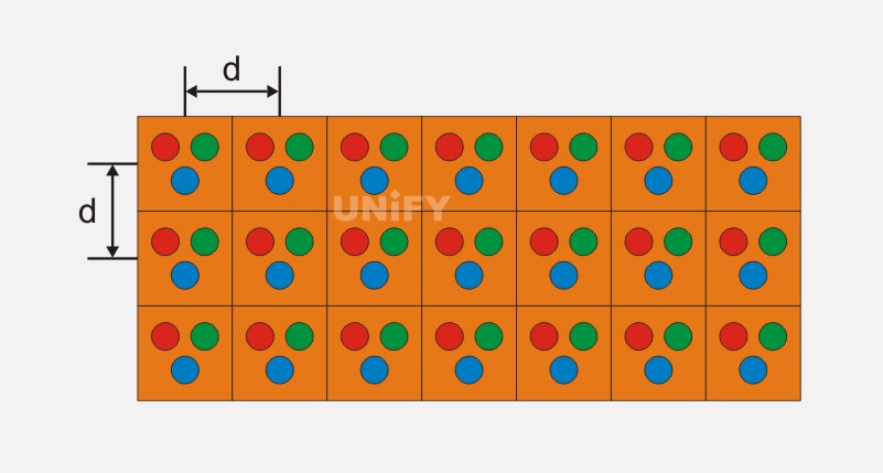
Pixel density
Pixel density refers to the number of pixels per unit area. Common units include PPI (Pixels Per Inch), that is, the number of pixels per inch. In the LED industry, pixel density is usually measured by the number of pixels per 1m². The higher the pixel value per unit area, the finer the image that the screen can display. Figure 1-10 shows a schematic diagram of pixel density.
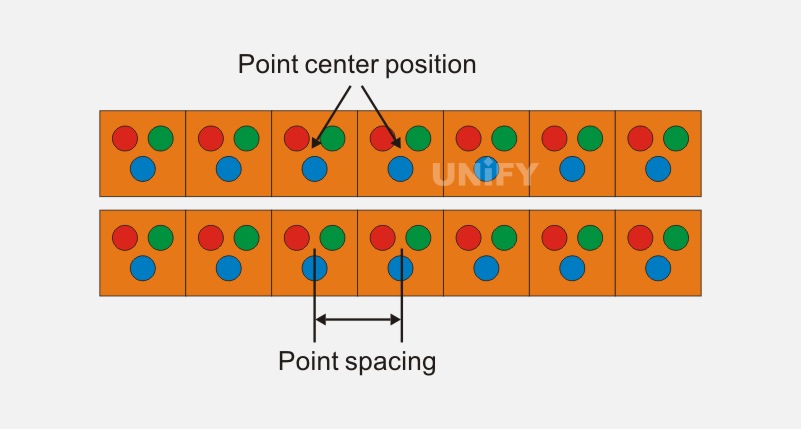
Dot pitch
The dot pitch refers to the center distance between pixels of the LED display screen, also known as the pixel pitch, and the unit is mm. The dot pitch diagram is shown in Figure 1-11. Since the English word for pixel is Pixel, the industry usually uses “P+ pitch value” to represent the dot pitch of a module, such as “P3” means that the dot pitch of the module is 3mm.
Resolution
Resolution is also called “pixel resolution”. An LED display is actually a pixel array composed of many LED lights. Resolution refers to the number of vertical and horizontal pixels in the pixel array. It is generally expressed in the form of “pixel width × pixel height”, such as “800 × 600”. The following are common resolutions in the industry.
(1) “720p” HD resolution: 1280 × 720 @ 60Hz (the “60Hz” here represents the frame rate, which will be described in detail later).
(2) “1080p” HD resolution: 1920 × 1080 @ 60Hz (where “p” stands for “progressive scan”, and “interlaced scan” corresponds to “1080i”).
(3) Full HD (FHD) resolution: 1920 × 1200 @ 60Hz.
(4) Ultra-high definition (UHD) resolution: 3840×2160@60Hz (this resolution is sometimes used in the industry to refer to “4K” resolution).
(5) “4K×1K” resolution: also known as “fake 4K” resolution, i.e. 4096×1080@60Hz or 4096×2160@30Hz (this resolution is sometimes used in the industry to refer to 3840×1080@60Hz or 3840×2160@30Hz).
(6) “4K×2K” resolution: also known as “true 4K” resolution, i.e. 4096×2160@60Hz (this resolution is sometimes used in the industry to refer to “UHD” resolution 3840×2160@60Hz).
Note: If the above common resolution abbreviations appear later, such as “1080p”, “4K×1K”, or “4K×2K”, please refer to the definitions here and no separate explanation will be given.
LED module
LED module , also known as LED light board, unit board, etc., is the smallest detachable unit that makes up the LED screen at the application level.
LED display cabinet
The LED display cabinet is composed of receiving cards, switching power supplies and modules arranged according to certain rules.
(1) The functions of the LED display cabinet are mainly manifested in the following two aspects.
① Fixing effect. Fix the display components such as light boards/modules and power supplies internally, and fix all components inside the cabinet to facilitate the connection and use of all display screens; fix the frame structure and steel structure externally.
② Protection effect. Protect the electronic components in the cabinet from interference from the external environment, and have an excellent protection effect.
(2) The classification of LED display cabinets is as follows.
① Cabinet material: The commonly used cabinet is an iron cabinet, and high-end cabinets can also be made of aluminum alloy or stainless steel.
② Waterproof function: LED display cabinets can be divided into waterproof cabinets and simple cabinets.
③ Device type: LED display cabinets can be divided into front-flip cabinets, double-sided cabinets, curved cabinets, etc.
LED screen
LED screen is a flat panel display composed of small LED module panels, which is used to display various information such as text, images, videos, and video signals.
Viewing distance
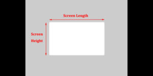
For various display devices, the best viewing distance should be the minimum distance at which the human eye cannot distinguish pixels. For LED display screens, in general, the minimum viewing distance is 1000 times the dot pitch, the best viewing distance is 3000 times the dot pitch, and the maximum viewing distance is 30 times the height of the display screen.
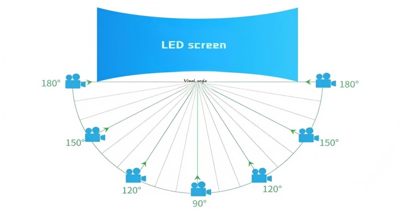
Viewing angle
When the observer faces the LED display screen, the maximum brightness of the LED display screen can be seen. When the observer moves to the left or right, the brightness of the screen seen will decrease. When the brightness value is reduced to half of the maximum brightness value, the sum of the angle at which the observer is located and the angle obtained by moving in the opposite direction is called the horizontal viewing angle. The vertical viewing angle can be measured in the same way. The horizontal and vertical viewing angles are shown in Figure 1-12.当
Brightness
Brightness refers to the luminous intensity per unit projection area in a given direction, and is the most important parameter in any display device. Its international unit is Candela, expressed in cd. The brightness of a single LED is usually expressed in mcd, which is one thousandth of a cd. Adding the brightness of 1m² of LEDs together gives the brightness per unit area.
Brightness: The human eye’s perception of the brightness of an object. The higher the brightness of a luminous object, the higher the brightness. The higher the reflectance of a non-luminous object, the higher the brightness.
Gamma γ
Gamma is used to represent the nonlinear relationship between brightness and input voltage.
Gamma value curve: Gamma value is the mathematical relationship between grayscale level and grayscale brightness, usually expressed as a curve, with grayscale level as the horizontal axis and grayscale brightness as the vertical axis. Therefore, the brightness and contrast of the image can be changed by adjusting the gamma value curve.
Grayscale
In the industry, the grayscale of a display usually refers to the brightness change that can be presented in the process of an LED display from a completely black state to the brightest state, and the unit is bit. In daily life, the grayscale of computer screens we come into contact with is mostly 8bit, which means that the computer screen can display a total of 2⁸=256 levels of grayscale from the darkest to the brightest. Therefore, we can imagine that for the concept of grayscale, the higher the grayscale level, the more delicate the image display of the screen, such as 10bit is 1024 levels of grayscale change.
In fact, most LED displays now have grayscales of more than 13 bits, up to 16 bits. If we hear a description like “the grayscale of a certain display is 14 bits”, it specifically means that the display can achieve 2¹⁴=16384 changes, but this only means that the display itself has the ability to output to 14 bits or even 16 bits. The actual output display effect also needs to consider the color bit depth of the input video source. It can be compared to a sports car that can reach a speed of 300km/h, but its actual driving speed does not depend on the maximum speed, but on the road speed limit. If the road speed limit is 80km/h, then no matter what its maximum speed is, the actual speed displayed is 80km/h. At present, the color bit depth of the input source is usually 8 bits, but the HDR video source requires a color bit depth of 10 bits, so HDR video can show more color combinations and image details.
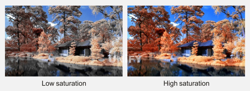
Saturation
Saturation refers to the vividness of the color, also known as the purity of the color. Saturation depends on the ratio of the chromatic component to the achromatic component (gray) in the color. The greater the chromatic component, the greater the saturation; the greater the achromatic component, the lower the saturation. Pure colors are highly saturated, such as bright red and bright green. When pure colors are mixed with white, gray, or other tones, they become unsaturated colors, such as crimson, pink, and yellow-brown. Completely unsaturated colors have no tones at all, such as the various grays between black and white. The saturation difference comparison is shown in Figure 1-13.
(a) Low saturation (b) High saturation
Figure 1-13 Saturation difference comparison
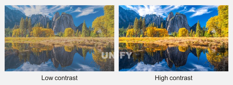
Contrast
Contrast refers to the measurement of the different brightness levels between the brightest white and the darkest black in the light and dark areas of an image, that is, the size of the grayscale contrast of an image. The larger the difference range, the greater the contrast, and the smaller the difference range, the smaller the contrast. Generally speaking, the greater the contrast, the clearer and more eye-catching the image, and the brighter the color; on the contrary, when the contrast decreases, the entire picture becomes gray. The contrast difference is shown in Figure 1-14. Figure 1-14 (b) shows a higher contrast, so the color levels of the house roof, the mountain rock, and the green plants all appear richer.
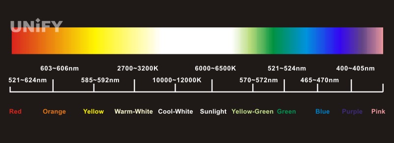
Color temperature
Color temperature refers to the color of an absolute black body after heating from absolute zero (-273℃). It is a unit of measurement for the color components contained in light. After being heated, the black body gradually changes from black to red, then turns yellow, white, and finally emits blue light. When heated to a certain temperature, the spectral components contained in the light emitted by the black body are called the color temperature at that temperature. The color temperature bar is shown in Figure 1-15. Its unit of measurement is “K” (Kelvin). If the light emitted by a certain light source contains the same spectral components as the light emitted by a black body at a certain temperature, it is called a “certain K” color temperature.
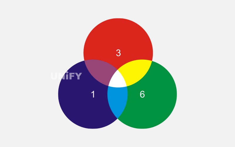
White balance
White balance is an indicator that describes the accuracy of the red, green and blue primary colors in the display medium to generate white. In LED display screens, the typical brightness ratio of the red, green and blue primary colors of white balance is 3 (red): 6 (green): 1 (blue). The white balance diagram is shown in the figure.
Busy intersections, commercial complexes, office buildings and park squares in the city: Due to their superior geographical location, these locations are important occasions for advertising . The installation of LED displays activates the vitality of the installation site and becomes a landscape of the city.
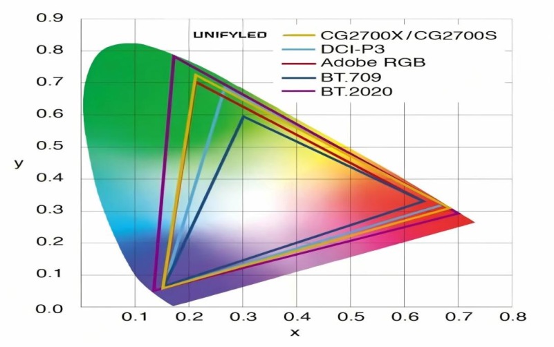
Color gamut
Color gamut refers to the range of colors that can be expressed by a certain color representation mode. Different industries have different requirements for the color gamut of display. In the LED display industry, the color gamuts commonly heard are DCI-P3, BT.709, BT.2020, sRGB, etc. The color gamut diagram is shown in Figure 1-17.
Frame rate
Frame rate refers to the number of frames or images shown or displayed per second, which is the concept of FPS (Frame Per Second). Frame rate is mainly used in the synchronization of audio and images in movies, TV or videos. The higher the frame rate, the smoother the picture. In daily life, the professional frame rate of movies is 24 frames per second.
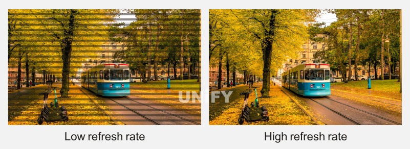
Visual refresh rate
The visual refresh rate of LED display is defined as: the number of times the image on the display is presented in full grayscale within 1 second. When the LED display is a scanning display, if the visual refresh rate is seriously insufficient, the human eye can perceive it.
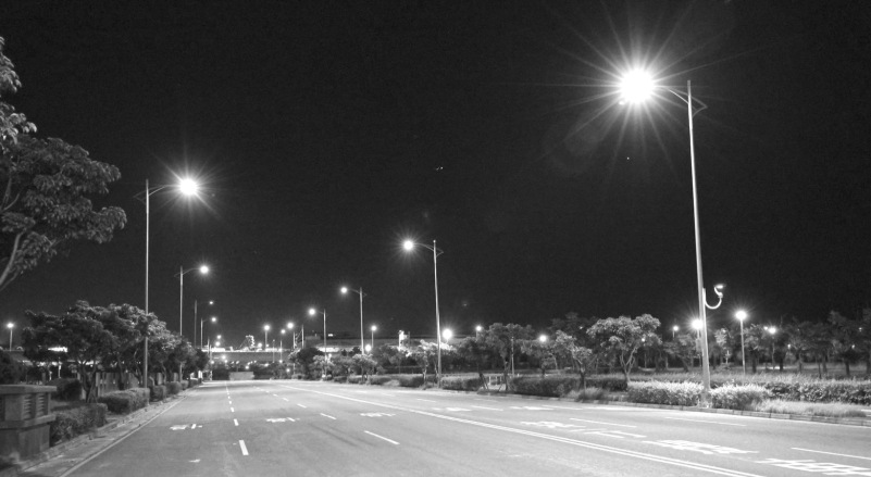
Generally, when the visual refresh rate is less than 240Hz, the human eye can feel the flicker of the screen. When using a high-speed shutter camera or video camera, it is very easy to capture black lines caused by insufficient refresh rate of the display. The black lines caused by insufficient refresh rate are shown in Figure 1-18.
When the grayscale level of the LED display is not high, there will be no black lines when taking pictures with a camera, but the grayscale effect of incompleteness will be captured, commonly known as “sweat spots” or “watermark” effect. The “sweat spots” effect caused by insufficient grayscale is shown in the figure
Insufficient refresh rate causes black lines in photos
The “sweat stain” effect caused by insufficient grayscale
By upgrading and improving the control system, we can ensure that the LED display screen has a high grayscale and refresh rate at the same time, and still has excellent performance under high-speed shutter shooting. The standard display screen photography effect is shown in the figure
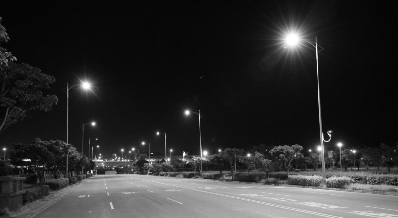
Standard display screen photography effect
Afterglow
After achieving high refresh rate and high grayscale, the scanning screen sometimes has very serious afterglow (also called ghosting or blanking). If a bright diagonal line is drawn on the display screen, the dark bright spot above the diagonal line is called the upward afterglow; the dark bright spot below the diagonal line is called the downward afterglow. Figure 1-21 shows the afterglow phenomenon of the scanning screen.
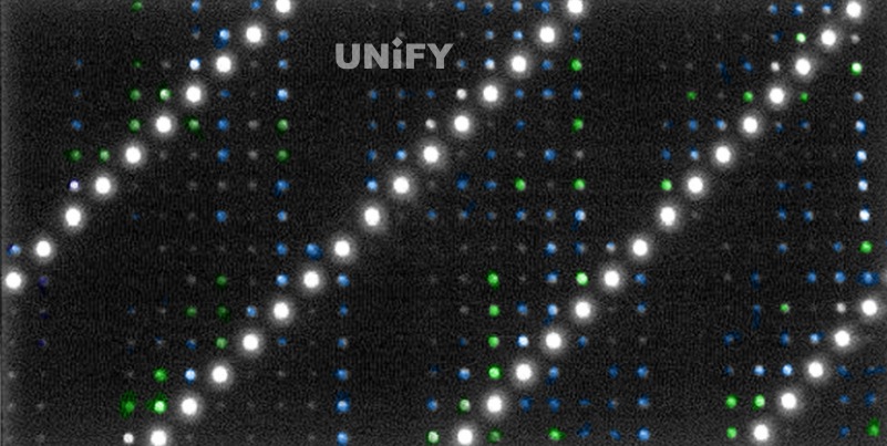
Scanning screen afterglow phenomenon
Eliminating afterglow requires two aspects:
(1) For uplink afterglow, discharge processing is required on the row line to eliminate it.
(2) For downlink afterglow, a driver chip with a pre-charge function is required to eliminate it through the cooperation of the control system. Currently, there are many driver chips with pre-charge function on the market. Combined with the timing adjustment of the control system, the downlink afterglow can be effectively eliminated. As shown in the figure, the row line is discharged using a chip with a pre-charge function. From the display effect, it can be seen that combined with the timing adjustment of the control system, the afterglow phenomenon can be basically eliminated even at a very high refresh rate.
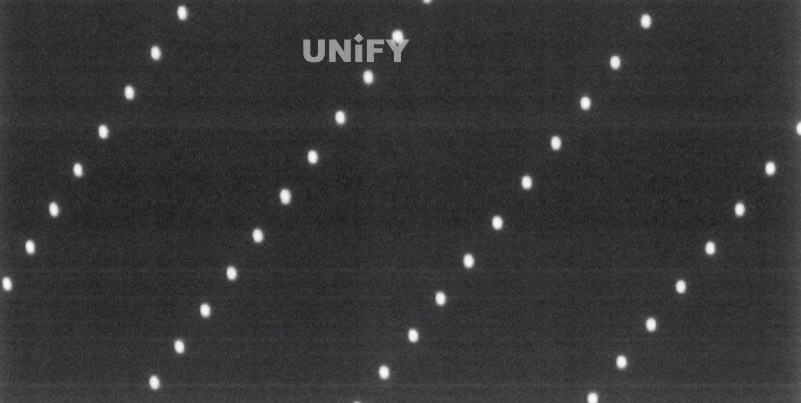
Driver chip with pre-charge function cooperates with row line discharge
Moiré
Moiré is a high-frequency interference on the photosensitive elements of digital cameras or scanners, which will cause colorful high-frequency stripes to appear in the image. Moiré is irregular, so there is no obvious shape pattern. For cameras, if a low-pass filter is installed on the lens during design, it will have a good effect in eliminating moiré, but it will affect the sharpness of the photo; for scanners, there is no good way to solve the moiré on them. Several common moiré patterns are shown in the figure.
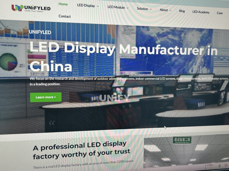
Photographing the moiré pattern on LCD monitors
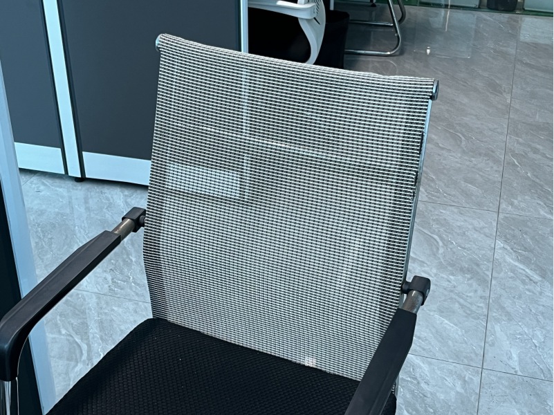
Photographing the moiré pattern that appears on dense mesh seat backs

Photographing the moiré pattern that appears on clothing with dense fiber stripes
In actual applications, moiré will also appear when we shoot LED displays. Is the appearance of moiré caused by poor display quality? No. Simply put, moiré is a manifestation of the beat principle. If the spatial frequency of the CCD (CMOS) pixel of the photosensitive element is close to the spatial frequency of the stripes in the image, moiré will appear.
To reduce and eliminate the effect of moiré in photography, the following four measures can be taken.
(1) Change the camera angle. Since the angle between the camera and the object can cause moiré to appear, slightly changing the camera angle (by rotating the camera) can change or eliminate any moiré that exists.
(2) Change the camera position. Changing the angle relationship by moving the camera left or right or up and down can also reduce moiré.
(3) Change the focus. Too sharp focus and high details on delicate patterns can cause moiré to appear. Slightly changing the focus can change the clarity and help eliminate moiré.
(4) Change the lens focal length. Moiré can be changed or eliminated by using different lenses or focal length settings.
Recommend Products
Indoor LED Screen Case in USA: Elevate Your Church Services
Indoor LED Screen Case in USA: Elevate Your Church Services Home Table of Contents IntroductionAs churches across the USA seek to engage congregations with richer audio-visual experiences, the adoption of LED display technology has surged. Indoor LED screens are now a central feature in worship spaces, transforming the way messages and media are presented.With vibrant

Synchronous Playback for LED Displays
Synchronized Playback for LED Displays Home Table of Contents Synchronized Playback for LED Displays After an LED display is configured, it needs to play content from a front-end input. When this content needs to be played in real-time, it is called synchronized playback for an LED display. Synchronized playback refers to the LED display playing
LED Display Basic Calculations
LED Display Basic Calculation Home Table of Contents Power Consumption Calculation In LED display related engineering projects, the power consumption of the screen power supply is a crucial parameter for evaluating screen performance and is closely tied to the safety of project construction. Incorrect calculation of the power consumption of an LED display in the early