Classification of LED Display ScreensLED
- Home
- »
- LED Academy
- »
- Classification of LED Display Screens
Table of Contents
Classification by use environment
1. Outdoor LED display screen
Outdoor LED display screens have a large area, generally ranging from a few square meters to dozens or even hundreds of square meters, with a large pixel pitch (mostly 2500-10000 pixels/m²), a luminous brightness of 5500-8500cd/m² (different orientations, different brightness requirements), and can be used under direct sunlight. The viewing distance is tens of meters away, and the screen has good wind, rain and lightning protection capabilities. Due to the harsh outdoor environment, outdoor modules are required to have good waterproof performance. Generally, the LED module is put into the kit and then glued to achieve waterproof effect. Due to the large outdoor viewing distance, the outdoor LED module has a higher luminous brightness. The outdoor LED display screen is shown in Figure.
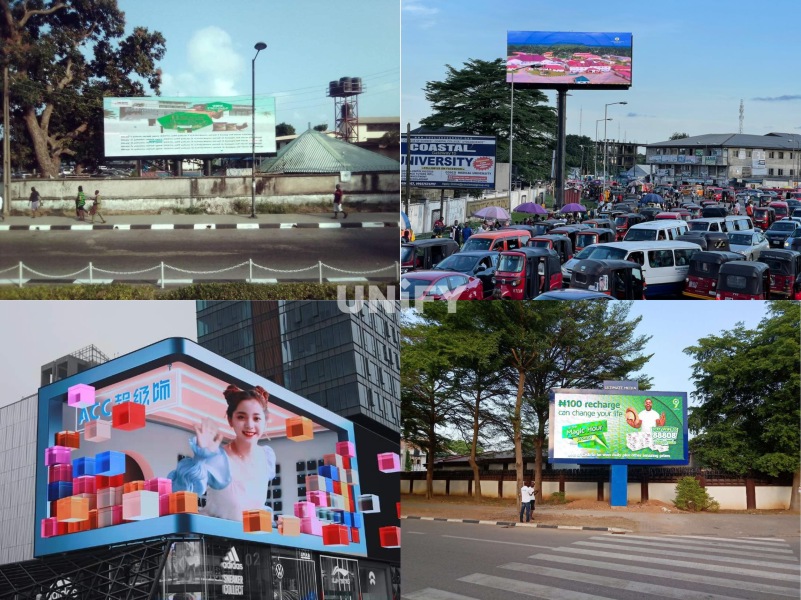
Outdoor LED Display
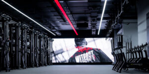
2. Indoor LED display
The area of indoor LED display varies depending on the use environment, generally ranging from a few square meters to more than ten square meters, or even hundreds of square meters. Because it is used in indoor environments and the viewing distance is relatively close, this type of display generally has a beautiful appearance design, high pixel density (number of pixels per unit area), large viewing angle, short color mixing distance, light weight, high density, and the luminous brightness cannot be too high. The indoor LED display is shown in the figure.
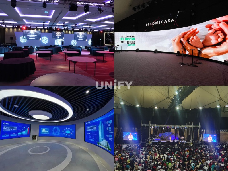
Indoor LED display
Classification by base color
1. Single-color LED display screen
Single-color LED display screen is composed of single-color modules, that is, each pixel is composed of LED lamp beads of only one color or one primary color. Since the wavelength of LED red light is longer and the brightness is higher, the common single-color modules are basically modules with red as the primary color. Single-color LED display screen is mainly used to display text information. For example, the door head screen installed above the bank entrance is used to display text information such as the current bank interest rate; and the strip screen installed above the counter is used to display the function description of the window or the order of the number. The application scenario of single-color LED display screen is shown in Figure 1-28.

Application scenarios of single-color LED display.
2. Surface Mount LED Display (SMD Package)
The LED lamp pins are directly soldered on the surface of the circuit board without passing through the circuit board. This method is called SMD (Surface Mount Device) packaging.
The LED packaged in this way is called surface mount LED, as shown in Figure 1-32. The surface mount LED display is composed of surface mount modules. The light source used in this type of module is surface mount three-in-one lamp beads. The packaging technology in the industry is also quite mature. Today, surface mount three-in-one lamp beads are still the mainstream lamp beads in the industry and are widely used in various display screens in the LED industry. The surface mount LED display was born after the direct plug-in LED display. At the beginning, it was mostly used indoors. Later, with the maturity of high-brightness surface mount LED lamp bead technology, it also began to be widely used outdoors.
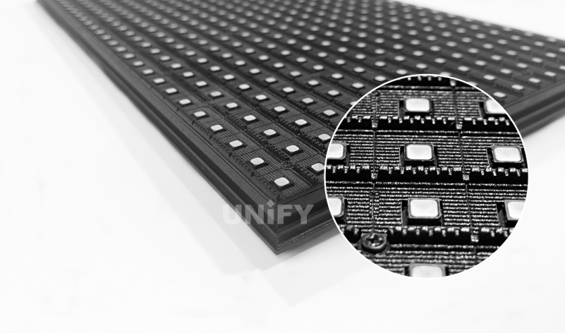
Surface Mount LED
3. Chip on Board LED Display (COB Package)
Packaging multiple lamp beads on a circuit board at one time is called COB (Chip on Board) packaging. LEDs packaged in this way are called chip on board LEDs, as shown in the figure.
The chip on board LED display consists of chip on board LED modules . It is a new packaging process in the industry. It abandons the traditional lamp bead packaging method in the industry and fixes the light-emitting chip directly on the PCB substrate. This packaging process can not only make the pixel pitch of the LED display smaller, but also reduce the entire production process. On the basis of future mature technology, it can greatly improve the production efficiency of the entire LED display and reduce production costs. Compared with direct-plug LED displays and surface-mount LED displays, chip on board LED displays have technical advantages such as smaller pixel pitch, anti-static, dustproof, and waterproof.
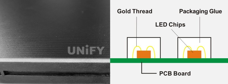
Chip-on-board LED
4. 4-in-1 Mini-LED display (1MD package)
4-in-1 Mini-LED is a small unit composed of two LED lamp beads in the horizontal and vertical directions, each of which is still packaged with RGB three-color chips. This packaging method is called IMD (Integrated Matrix Devices) packaging in the industry. The 4-in-1 Mini-LED is shown in the figure. The display composed of 4-in-1 Mini-LED modules is called 4-in-1 Mini-LED display. This technology is an improvement in conquering small pitch. In simple terms, SMD is a discrete device, COB is an integrated package chip, and IMD can be understood as a small integrated package of high-speed patch. Different from SMD and COB, IMD is a new generation product that integrates the advantages of two technical paths.
Four-in-one Mini-LED
Classification by application scenario
1. Fixed screen
Fixed screen refers to an LED display screen that is fixedly installed at a designated location. In normal use, it does not need to be disassembled or moved after installation, so it only needs to meet the environment and viewing requirements.
2. Rental screen
Rental screens are generally used in temporary performances, evening parties, exhibitions and other sites. This type of LED display screen generally has the characteristics of frequent disassembly, high installation efficiency requirements, and strong instant viewing. Therefore, the rental screen has good protection, easy installation structure, and convenient disassembly and assembly of components.
Common interface types in the industry
1.DVI
DVI (Digital Visual Interface) is a technology for high-speed transmission of digital signals invented by the Digital Display Working Group (DDWG) established in the Intel Developer Forum in September 1998. There are three different types of interfaces: DVI-A, DVI-D and DVI-I. DVI-D has only digital interfaces, while DVI-I has both digital and analog interfaces. Currently, DVI-D (24+1) is the main application.
DVI and VGA interfaces are the most commonly used interfaces in computers. Unlike VGA interfaces, DVI can transmit digital signals without digital/analog conversion, so the picture quality is very high. Currently, DVI is also provided on many high-definition TVs. It should be noted that DVI has multiple specifications, the most common of which are DVI-D (Digital)
and DVI-I (Intergrated). DVI-D can only transmit digital signals and can be used to connect graphics cards and flat-panel TVs. DVI-I can not only transmit digital signals, but also analog signals, and can be converted to and from the VGA interface.
The maximum resolution and transmission rate supported by different types of DVI are shown in the table.
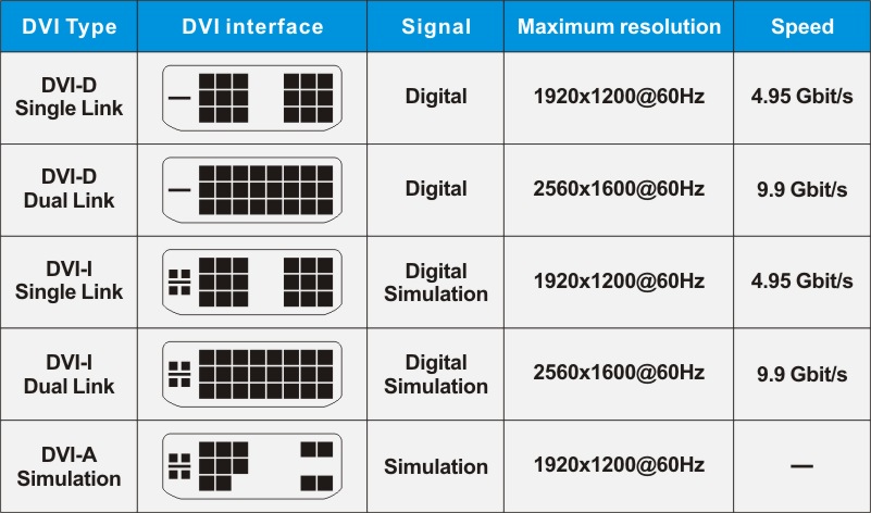
The highest resolution and transmission rate supported by different types of DVI
2.HDMI
High Definition Multimedia Interface (HDMI) is an interface standard that has both high-definition digital video and digital audio transmission capabilities. It is a dedicated digital interface suitable for image transmission. It can transmit audio and image signals at the same time. The maximum data transmission rate is 18Gbit/s, and there is no need to perform digital/analog or analog/digital conversion before signal transmission. HDMI cable is a fully digital image and sound transmission cable that can be used to transmit uncompressed audio and video signals.
HDMI has the advantages of small size, high transmission rate, wide transmission bandwidth, good compatibility, and the ability to transmit uncompressed audio/video signals at the same time. The HDMI schematic diagram is shown in the figure.
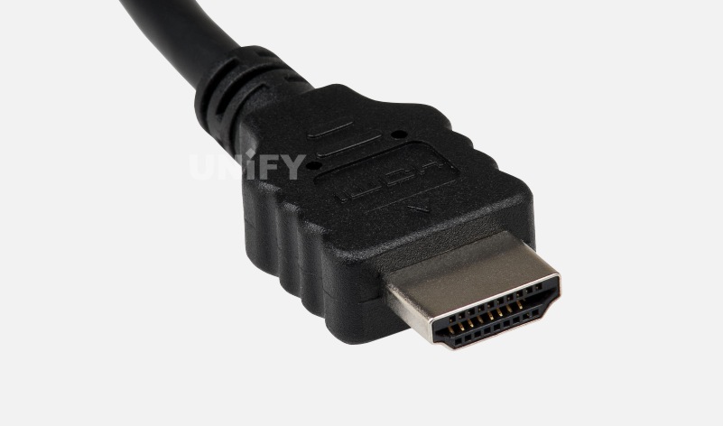
HDMI Diagram
Compared with DVI, HDMI can transmit digital audio signals, and adds support for HDCP (High-bandwidth Digital Content Protection), while providing better DDC optional functions. HDCP technology can interfere with illegal copying of high-definition signals by users, reducing the quality of the copied images, thereby protecting the copyright of the content. The transmission rates and maximum resolutions corresponding to different HDMI interface versions are shown in the table.
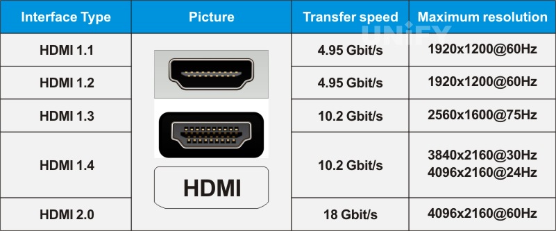
Table 1-2 Transmission rates and maximum resolutions corresponding to different HDMI interface versions
Note: The HDMI cable length is not recommended to exceed 15m, otherwise the picture quality will be affected.
3.DP
DisplayPort (DP for short) is a digital video interface standard jointly developed by personal computer and chip manufacturers and standardized by the Video Electronics Standards Association (VESA). This interface is free of certification and licensing fees. It is mainly used to connect video sources with devices such as monitors, and also supports carrying audio, USB and other forms of data.
As the successor to DVI, DP will add the transmission of high-definition audio signals while transmitting video signals, and support higher resolutions and refresh rates.
Like HDMI, DP also allows audio and video signals to share a cable for transmission, supporting a variety of high-quality digital audio. But more advanced than HDMI is that DP can achieve more functions on a single cable. In addition to the four main transmission channels, DP also provides a powerful auxiliary channel with a transmission bandwidth of 1Mbit/s and a maximum delay of only 500μs. It can be directly used as a transmission channel for low-bandwidth data such as voice and video, and can also be used for delay-free game control.
DP is backward compatible with traditional interfaces such as HDMI and DVI through active or passive adapters. DP is designed to support both external display connections and built-in display connections. VESA hopes that notebook computer manufacturers will use DP not only to connect independent monitors, but also to directly connect LCD screens and motherboards to facilitate notebook computer upgrades. To this end, DP is designed to be very compact, which is convenient for notebook computer use and allows graphics cards to be configured with multiple interfaces.
Currently, there are two types of external interfaces for DP: one is the standard type, similar to USB, HDMI and other interfaces. The schematic diagram of the standard DP is shown in Figure 1-36; the other is the low-profile type, which is mainly aimed at applications with limited connection area, such as ultra-thin notebook computers.
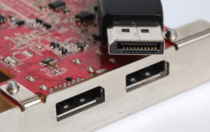
Standard DP schematic diagram
The transmission rates and maximum resolutions corresponding to different EP interface versions are shown in the table below.
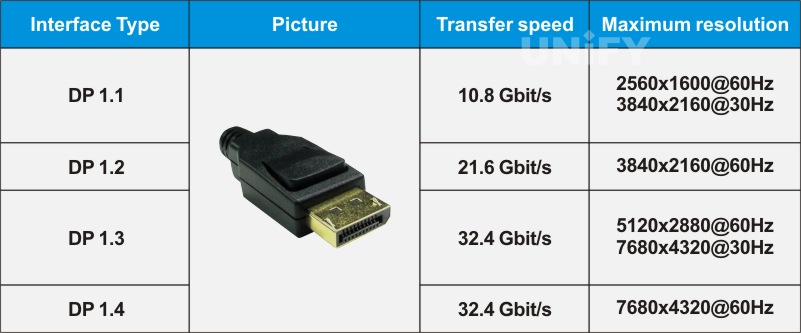
DP different interface versions corresponding to the transmission rate and maximum resolution
4 VGA interface
VGA (Video Graphic Array) interface, also known as D-Sub interface, VGA interface diagram is shown in . VGA interface is the interface for outputting analog signals on the graphics card. Although LCD monitors can directly receive digital signals, many low-end products use VGA interface to match VGA interface graphics cards. VGA interface is a D-type interface with 15 pinholes in total, divided into 3 rows, 5 pinholes in each row. It can transmit red, green, blue analog signals and synchronization signals (horizontal and vertical signals).
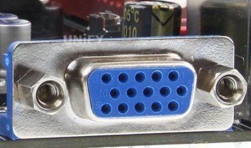
VGA interface diagram
When connecting devices using the VGA interface, the cable length should not exceed 10m, and attention should be paid to whether the connector is firmly installed to avoid ghosting in the image.
Various VGA cables can support a variety of resolutions, ranging from 320×400 @70 Hz/320×480 @ 60Hz (12.6 MHz signal bandwidth) to 1280×1024 (SXGA)@85Hz(160MHz), and even up to 2048×1536 (QXGA)@85 Hz(388 MHz).
VGA interface can transmit red, green, blue analog signals and synchronization signals (horizontal and vertical signals). VGA interface supports 16 colors and 256 grayscales at 640×480 resolution, or 256 colors at 320×240 resolution. Later, based on this, expanded modes with higher resolutions such as 800×600 (SVGA) or 1024×768 (XGA), 1280×1024 (SXGA) were introduced. These modes still use the same interface plug-in as before, that is, a 15-pin trapezoidal plug to transmit analog signals.
The resolutions supported by the VGA interface are shown in the tableVGA.

Resolutions supported by the VGA interface
Currently, the VGA standard is outdated for the personal computer market, but VGA is still the minimum standard supported by all manufacturers. For example, no matter which manufacturer’s graphics card supports VGA standard display.
The VGA interface still transmits analog signals. For the display image information generated in digital form, it is converted into R, G, B three primary color signals and horizontal and vertical synchronization signals through a digital/analog converter. The signal is then transmitted to the display device through a cable. The image loss during the conversion process will slightly reduce the display effect.
5 CVBS interface
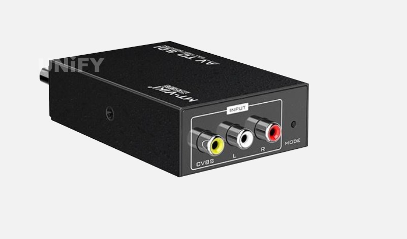
CVBS stands for “Composite Synchronous Video Broadcast Signal” or “Composite Video Blanking and Synchronization” in Chinese. It is an older display method. The CVBS interface is an interface for separating audio and video. It is generally composed of three independent RCA plugs (also known as plum blossom interface, RCA interface). The CVBS interface connects the mixed video signal, which is a yellow socket; the L interface connects the left channel sound signal, which is a red socket; the R interface connects the right channel sound signal, which is a white socket.
CVBS is also a widely used standard, also known as baseband video or RCA video. It is the traditional image data transmission method of the National Television Standards Committee (NTSC) television signal of the United States. It transmits data in an analog waveform. Composite video contains color difference (hue and saturation) and brightness (brightness) information, and synchronizes them in the blanking pulse and transmits them with the same signal. The CVBS interface is still used in some low-end cameras. The external output interface is generally in the form of BNC.
The schematic diagram of the CVBS interface is shown in Figure.
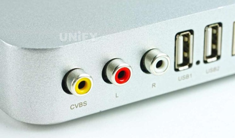
CVBS interface diagram
6 AV interface
AV interface is also called AV terminal or composite terminal. It is a common terminal used by home audio and video appliances to send video analog signals (such as NTSC, PAL, SECAM). AV interface usually uses yellow RCA interface to transmit video signals, and two red and white RCA interfaces to transmit audio signals, so it is also called three-color line/red, white and yellow line. AV interface diagram is shown in the figure
AV interface diagram
The standard video input interface, also known as the AV interface, is a pair of white audio interface and yellow video interface. It uses RCA (commonly known as lotus head) for connection. When using it, you only need to connect the standard AV cable with lotus head to the corresponding interface. The AV interface realizes the separation of audio and video transmission, avoiding the image quality degradation caused by audio/video mixing interference, but because the AV interface still transmits a brightness/chroma (Y/C) mixed video signal, the display device still needs to perform brightness/chroma separation and chroma decoding to image it. This process of mixing and then separating will inevitably cause the loss of color signals, and the chroma signal and the brightness signal are likely to interfere with each other, thus affecting the final output image quality. The AV interface still has a certain vitality, but its own brightness/chroma mixing, an insurmountable disadvantage, makes it impossible to use it in some occasions that pursue the visual limit.
7 SDI
SDI (Serial Digital) is a series of digital video interfaces, first proposed by the Society of Motion Picture and Television Engineers (SMPTE) in 1989 and used for broadcast-level video.
The SDI standard specifies the transmission of uncompressed serial digital video data between product devices via video coaxial cable. The data rate of SDI signals is very high, so they must be processed before transmission. People often embed digital audio signals in SDI signals, that is, insert digital audio signals into the line and field synchronization pulses (line and field blanking) of the video signal and transmit them simultaneously with the digital component video signal.
According to the transmission rate of SDI, SDI signal standards are divided into standard definition SD-SDI, high definition standard HD-
SDI, 3G-SDI, 6G-SDI and 12G-SDI. SDI uses BNC interface. The schematic diagram of SDI interface is shown in Figure 1-40. It uses coaxial cable for transmission and the effective transmission distance is 100m. The transmission rate and maximum resolution corresponding to different versions of SDI interface are shown in the table
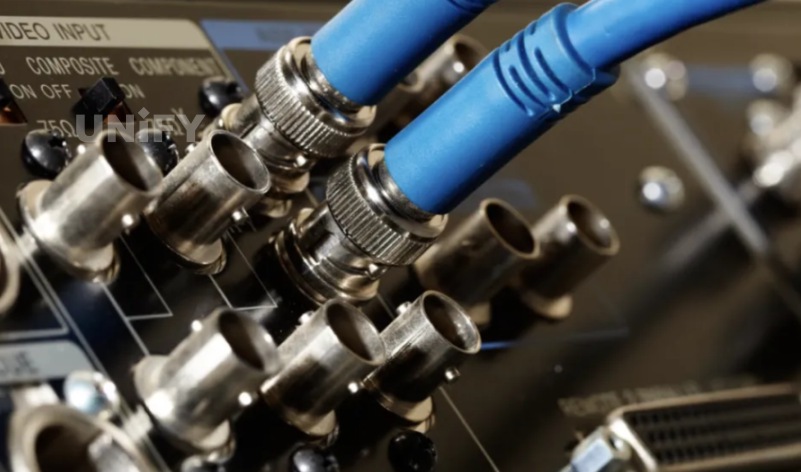
SDI interface diagram
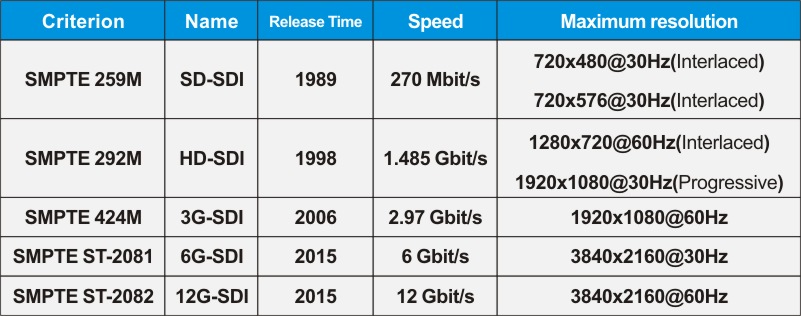
Transmission rate and maximum resolution corresponding to different versions of SDI interface
8 RJ45 interface
RJ is the abbreviation of Registered Jack, which means “registered socket”. It is defined in the standards and regulations of the FCC (Federal Communications Commission) as follows: RJ is an interface that describes the public telecommunications network, and RJ45 is the common name for the standard 8-bit modular interface.
The RJ45 connector consists of a plug and a socket. The connector composed of these two components is connected between the wires to achieve electrical continuity of the wires. The schematic diagram of the RJ45 interface is shown in the figure. The RJ45 connector is the most important socket among connectors, which is divided into shielded and unshielded types. The RJ45 interface supports three speeds of 10M/100M/1000Mbit/s, and has the automatic negotiation function of receiving and sending and speed mode.
The internationally recognized network cable standards are divided into seven categories. Currently, the commonly used ones are Category 5, Category 5e and Category 6. All three are composed of four pairs of twisted pairs. The difference is that Category 5e has a higher winding density than Category 5, which makes the crosstalk smaller, the transmission distance longer, and the transmission bandwidth wider. Category 6 increases the diameter of the cable on the basis of Category 5e and adds an insulating groove in the middle of the cable, which further improves the signal-to-noise ratio.

RJ45 interface diagram
Category 5 network cables are suitable for 100M Ethernet, while Category 5e and Category 6 network cables are suitable for Gigabit Ethernet.
The commonly used network cable sequence in the LED display industry is the T568B version, and the corresponding RJ45 network cable plug pin number and network cable color are shown in the table.
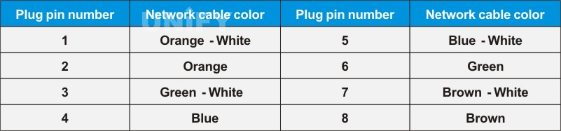
Correspondence between RJ45 network cable plug pin number and network cable color
9 RS232 interface
The RS232 interface is an asynchronous transmission standard interface established by the Electronic Industries Association (EIA). Usually the RS232 interface appears in the form of 9 pins (DB9) or 25 pins (DB25). The RS232 interface diagram is shown in the figure.
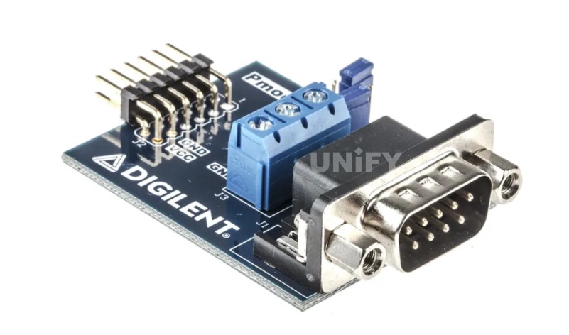
RS232 interface diagram
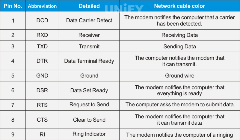
RS232 Pin Definition
RS232 communication requires multiple settings in the software settings. The most common settings include baud rate, parity check, and stop bit.
(1) Baud rate refers to the baud rate sent from one device to another, that is, the number of symbols transmitted per second. Typical baud rates are 300, 1200, 2400, 9600, 19200, 115200, etc. Generally, the devices at both ends of the communication should be set to the same baud rate, but some devices can also be set to automatically detect the baud rate.
(2) Parity check is used to verify the correctness of the data. Parity check is generally not used. If used, it can be either odd parity or even parity. Parity check works by modifying each sent byte (or limiting the bytes sent). If parity check is not performed, the data will not be changed. In even parity, because the parity bit will be set to “1” or “0” accordingly (usually the highest or lowest bit), the data will be changed so that the number of “1” in all transmitted bits (including the bits of the characters and the check bits) is an even number; in odd parity, the number of “1” in all transmitted bits (including the bits of the characters and the check bits) is an odd number. Parity check can be used by the receiver to check whether there is an error in the transmission – if the number of “1” in a byte is wrong, then this byte must have an error in the transmission. If the parity check is correct, then either no error occurred or an even number of errors occurred. If the user selects the data length to be 8 bits, since there are no extra bits to be used as bits, it is called non-parity check.
(3) The stop bit is sent after each byte is transmitted, which is used to help the hardware of the receiving signal resynchronize.
It should be noted that the maximum communication distance of RS232 is 15m.
10 GENLOCK interface
GENLOCK (synchronous lock) is a common video processing equipment technology that uses the video output of one source (or a specific reference signal from a signal generator) to synchronize other video sources together. The purpose of GENLOCK is to ensure the consistency of multiple video signals at the splicing or switching time point.
When video devices are synchronized in this way, they are called synchronous lock or generator lock. Usually GENLOCK is used to solve display synchronization problems that may be encountered on site, such as screen tearing, scan line problems, etc.
The GENLOCK interface generally uses a BNC connector. The schematic diagram of the GENLOCK interface is shown in Figure. According to the different synchronization source signals, GENLOCK is divided into Black Burst and Tri-Level.

GENLOCK interface diagram
(1) Black Burst is a dual-level synchronization, which is a composite video signal with a black field image. As a reference signal for synchronizing video devices, it can enable multi-mode video devices to output video signals with the same timing, while also ensuring seamless switching between two video signals. The timing accuracy can reach tens of nanoseconds, which is sufficient for common video display scenarios. Since Black Burst is an ordinary video signal, it can be transmitted through common video cables and distributed through video distributors.
(2) Tri-Level is a three-level synchronization, and the video synchronization principle is the same as Black Burst. However, it has a higher frequency than Black Burst, so the synchronization clock jitter is smaller and the overall synchronization signal is more stable. In addition, the Tri-Level pulse signal is in two polarities, so there is no DC component in its transmission path, and the signal noise is also better.
It is an industry trend for Tri-level to replace Black Burst. Although Black Burst is currently used more in the industry, high-end equipment has begun to slowly transition to Tri-level.
Recommend Products
Indoor LED Screen Case in USA: Elevate Your Church Services
Indoor LED Screen Case in USA: Elevate Your Church Services Home Table of Contents Introduction As churches across the USA seek to engage congregations with richer audio-visual experiences, the adoption of LED display technology has surged. Indoor LED screens are now a central feature in worship spaces, transforming the way messages and media are presented.

Synchronous Playback for LED Displays
Synchronized Playback for LED Displays Home Table of Contents Synchronized Playback for LED Displays After an LED display is configured, it needs to play content from a front-end input. When this content needs to be played in real-time, it is called synchronized playback for an LED display. Synchronized playback refers to the LED display playing
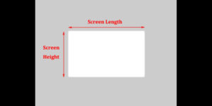
LED Display Basic Calculations
LED Display Basic Calculation Home Table of Contents Power Consumption Calculation In LED display related engineering projects, the power consumption of the screen power supply is a crucial parameter for evaluating screen performance and is closely tied to the safety of project construction. Incorrect calculation of the power consumption of an LED display in the early