Synchronized Playback for LED Displays
- Home
- »
- LED Academy
- »
- Synchronous Playback for LED Displays
Table of Contents
Synchronized Playback for LED Displays
After an LED display is configured, it needs to play content from a front-end input. When this content needs to be played in real-time, it is called synchronized playback for an LED display. Synchronized playback refers to the LED display playing a video source provided by the front end in real-time.
Table 1-1 lists the basic hardware required for synchronous video source playback.
Table 1-1 Basic Hardware Devices Required for Synchronous Playback of Video Sources
| Device Name | Device Function |
|---|---|
| Computer/Multimedia player box, etc. | Provide standard video source output |
| Sending card/Controller | Receive the video source from the front-end computer/multimedia player box and send it to the LED display |
| LED display | Receive the video source from the front-end sending card/controller and display it |
The system structure for synchronized video source playback on an LED display is shown in Figure 6-1. The computer, sending card/controller, and LED display are the most basic hardware components for achieving synchronized playback. Through this system, the front-end video source can be displayed on the LED display in real-time. To ensure the actual playback effect, resolution issues must also be considered. There is a corresponding relationship between the front-end video source resolution, the sending card/controller resolution, and the LED display resolution. Only when the resolutions of the three reach a corresponding proportional relationship can the LED display present the ideal playback effect.
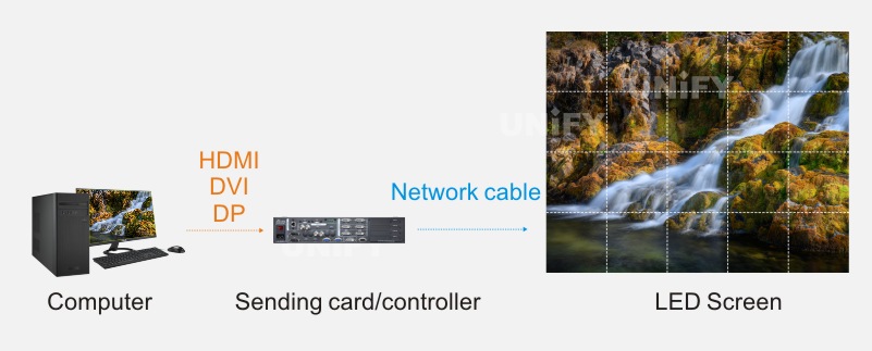
Figure 6-1 System Structure for LED Display Synchronized Video Source Playback
According to how the video source is presented, synchronized video source playback can be divided into two types: direct video source playback and video source effects playback, which are introduced below.
Direct Video Source Playback
Direct video source playback refers to displaying the video source output from a front-end multimedia device directly onto the LED display via a sending card/controller.
Under normal circumstances, the content displayed on the LED display is the complete video source content. The front-end video source, after passing through the sending card/controller, is displayed on the LED display with a one-to-one correspondence between the video source pixels and the LED display pixels, which is called point-to-point display. At this time, if you want the LED display to show the complete video source content in full screen, you must ensure that the resolution of the video source, the resolution of the sending card/controller, and the resolution of the LED display are exactly the same. Taking the 1080p (1920×1080@60Hz) standard resolution as an example, its point-to-point display principle is shown in Figure 6-2.
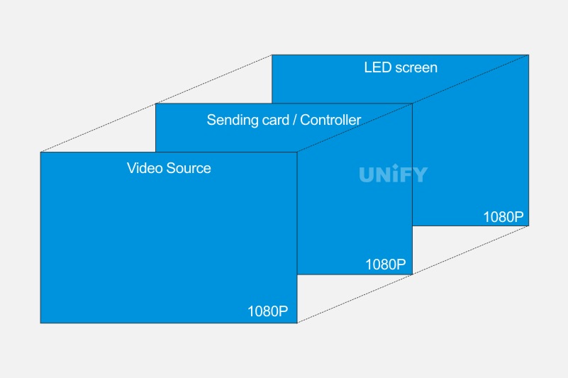
Figure 6-2 Point-to-Point Display Principle for 1080p Standard Resolution
The resolutions of the video source and the sending card/controller are editable; however, the resolution of the LED display is determined by the actual size of the LED display and is not editable.
When the front-end multimedia device is a computer, the required video source resolution can be obtained by setting the output resolution of the computer’s graphics card. Taking two graphics cards as examples, the settings are shown in Figures 6-3 and 6-4.
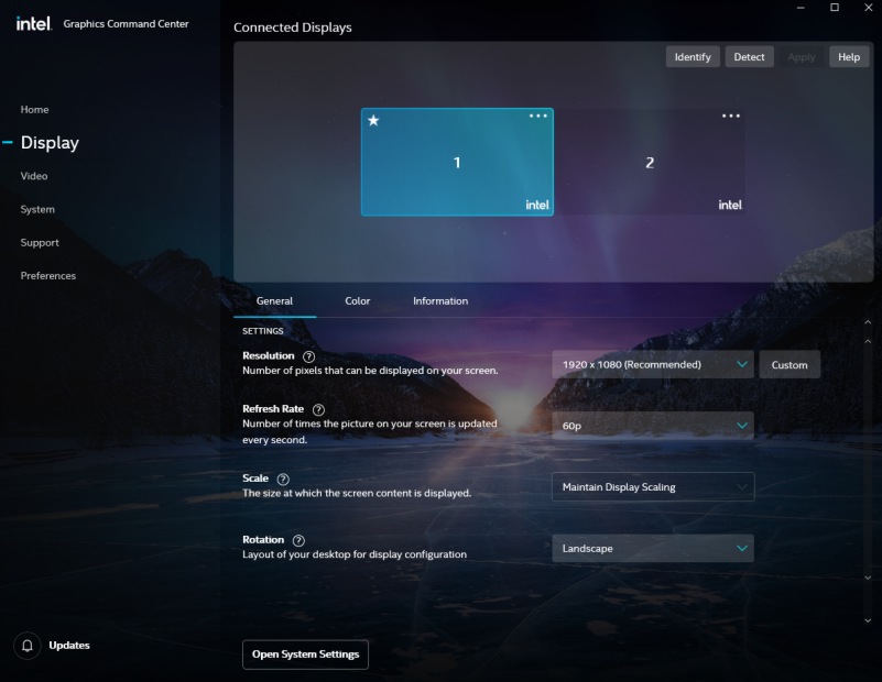
Figure 6-3 Setting Video Source Resolution in Intel Graphics Command Center
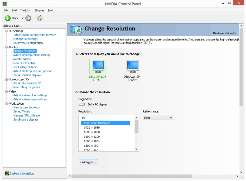
Figure 6-4 Setting Video Source Resolution in Nvidia Control Panel
The resolution of the sending card/controller can be set in two ways: through the NovaLCT control software or the sending card’s front panel.
Setting via NovaLCT control software: Log in and open the NovaLCT control software, then click the “Screen Configuration” icon, as shown in Figure 6-5. In the “Screen Configuration” dialog box, on the “Sending Card” tab, you can follow the steps shown in Figure 6-6 to set the resolution of the sending card/controller.
Step 1: Check the sending card’s current resolution on the “Sending Card” tab.
Step 2: Select the correct sending card resolution (consistent with the graphics card output resolution, i.e., the video source resolution), or you can set a custom sending card resolution.
Step 3: Click the “Set” button. If there is only one sending card, you can set it directly; if there are multiple, you need to select the corresponding sending card.
Step 4: Select the corresponding sending card.
Step 5: Click the “OK” button to set the sending card resolution.
Step 6: Click the “Refresh” button to confirm that the sending card resolution has been set successfully.
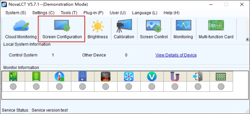
Figure 6-5 Entering Screen Configuration via NovaLCT Control Softwar
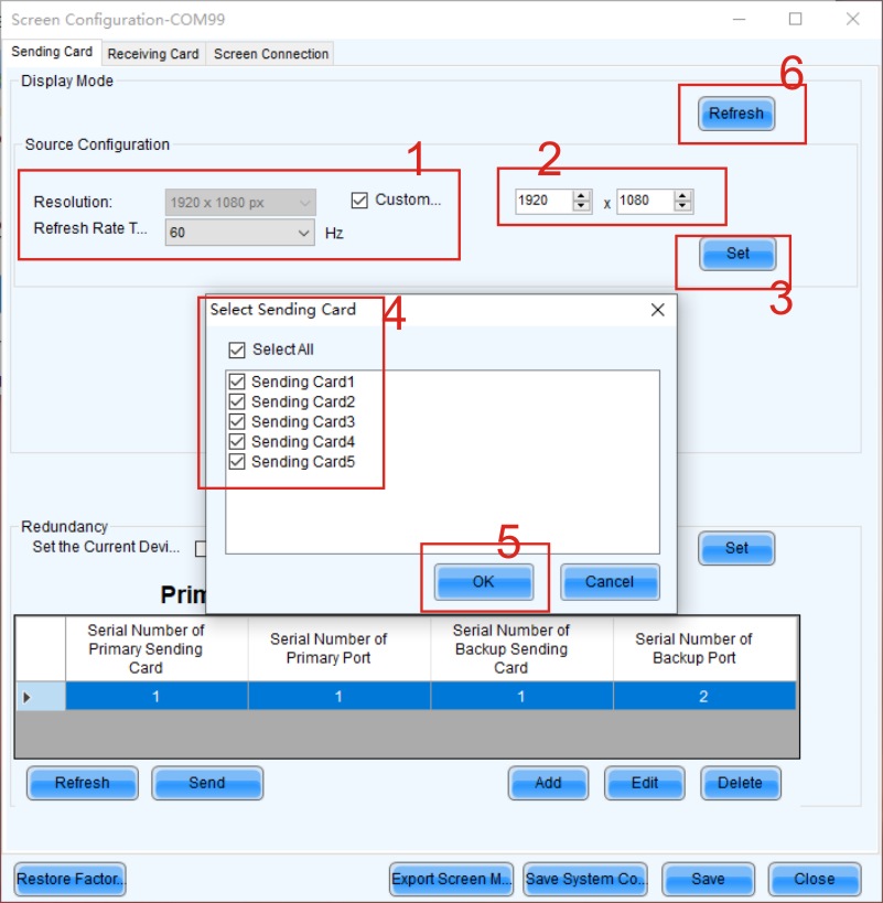
Figure 6-6 “Sending Card” Settings Interface
Setting via the sending card’s front panel:
Taking NovaStar’s MCTRL660PRO controller as an example, the steps to set the resolution are as follows: use the knob to sequentially select the “Input Setup” → “Preset Resolution” → “Preset Resolution Setup” command (custom resolution is similar), as shown in Figure 6-7.
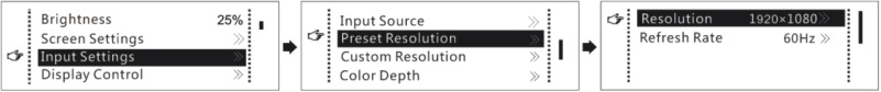
Figure 6-7 Steps to Set Resolution via the Sending Card’s Front Panel
Through the above steps, the resolutions of the video source, the sending card/controller, and the LED display can be kept consistent, thereby achieving direct playback of the complete video source. However, in most cases, the resolution of an LED display LED is not a standard resolution. If the front-end multimedia device cannot output a video source with the same resolution as the LED display, it will not be possible to play the video content completely. In this case, professional playback software such as “Screen Master” is needed.
Video Source Effects Playback
When the front-end multimedia device cannot output a video source with the same resolution as the LED display, and the resolution of the front-end output video source is greater than the resolution of the LED display, you can use NovaStar’s playback software “Screen Master” to ensure that the LED display can completely play the video source content.
The working principle of Screen Master is to set a playback window on the front-end video source computer’s desktop with a starting position of (0,0) and map the window’s position to the full-screen range of the LED display, which means setting the playback window’s resolution to be the same as the LED display’s resolution.
1. Using Playback Software for Video Source Effects Playback
Taking an LED display with a resolution of 1366×768 as an example, the specific operating steps are as follows.Add a regular screen in “Local Playback” mode, as shown in Figure 6-8.
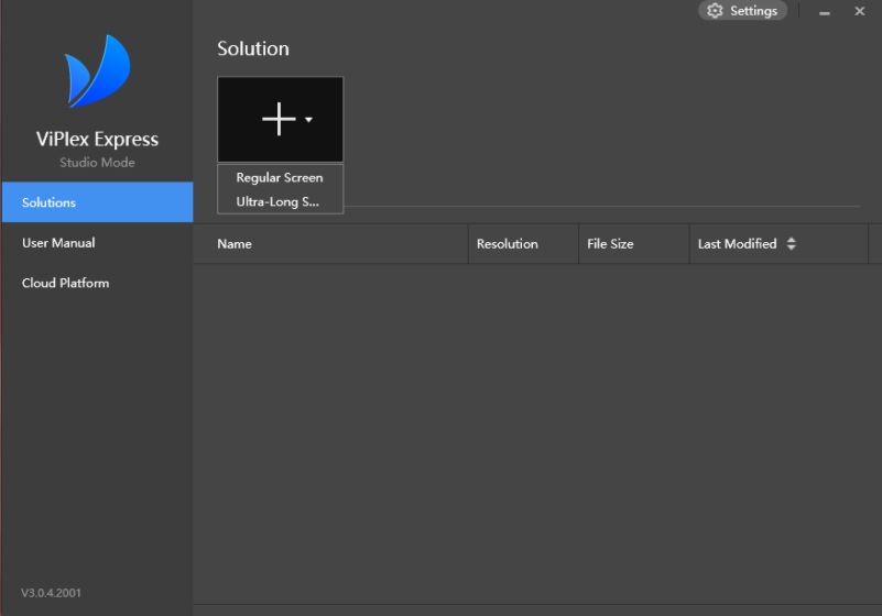
Figure 6-8 Adding a Regular Screen
Enter the “Playback Window Setup” interface, as shown in Figure 6-9.
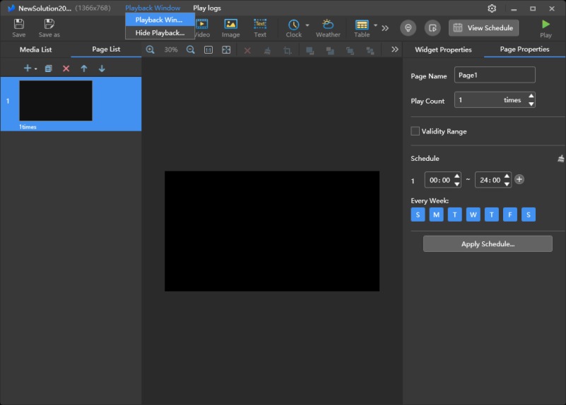
Figure 6-9 “Playback Window Setup” Interface
Open the “Playback Window Setup” dialog box and set the playback window size and starting position information (taking a resolution of 1366×768 as an example), as shown in Figure 6-10.
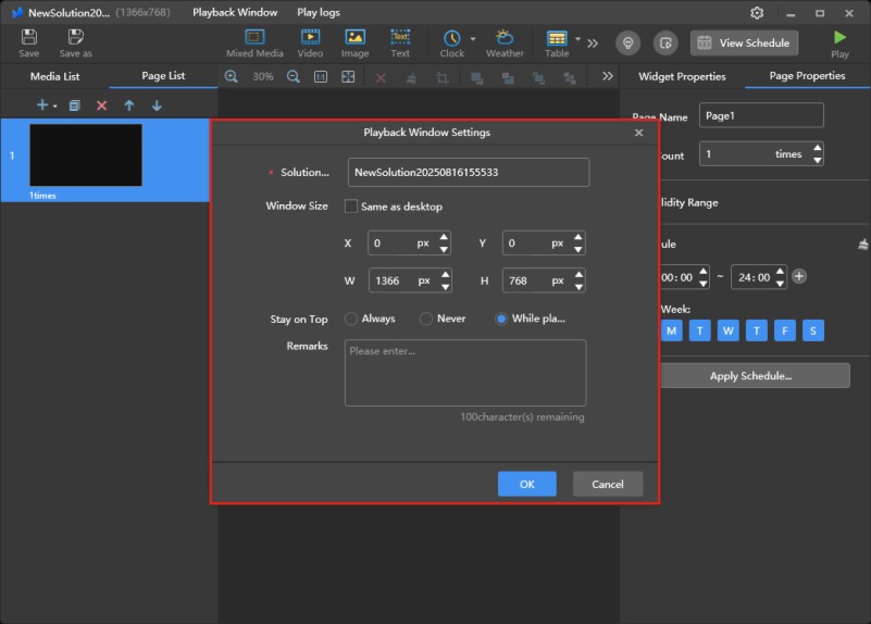
Figure 6-10 Setting Playback Window Size and Starting Position Information (Resolution of 1366×768 is used as an example)
Add a general window for the playback content, set the general window’s starting position and size (taking a resolution of 1366×768 as an example), and add the playback content by finding and opening the desired content in the corresponding path, as shown in Figure 6-11.
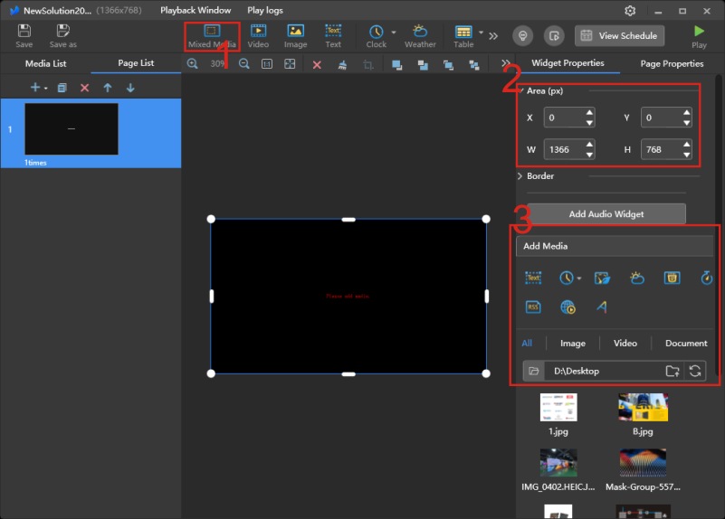
Figure 6-11 Steps for Adding a General Window and Content
The Screen Master playback software allows setting playback properties for the added components, supporting settings for playback duration, number of plays, entry effects, and effect duration, as shown in Figure 6-12.
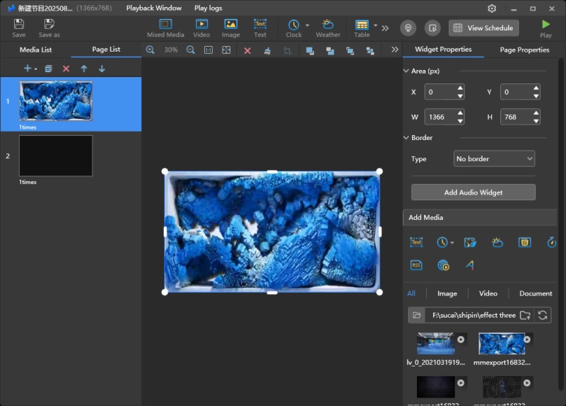
Figure 6-12 Playback Property Settings
The Screen Master playback software can set properties for the added pages, supporting the setting of properties such as playback times, start/end dates, a time schedule, and a playlist, as shown in Figure 6-13.
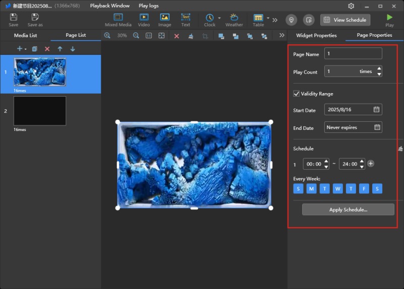
Figure 6-13 Page Property Settings
After setting up the program to be played, to ensure that the program’s effect is normal, we can check the final program playback effect by clicking the “Preview” button in the top right corner. After confirming that everything is correct, we can proceed with the actual playback operation. The playback window playback preview and the display effect of the playback window on the computer’s desktop are shown in Figures 6-14 and 6-15.

Figure 6-14 Playback Window Playback Preview
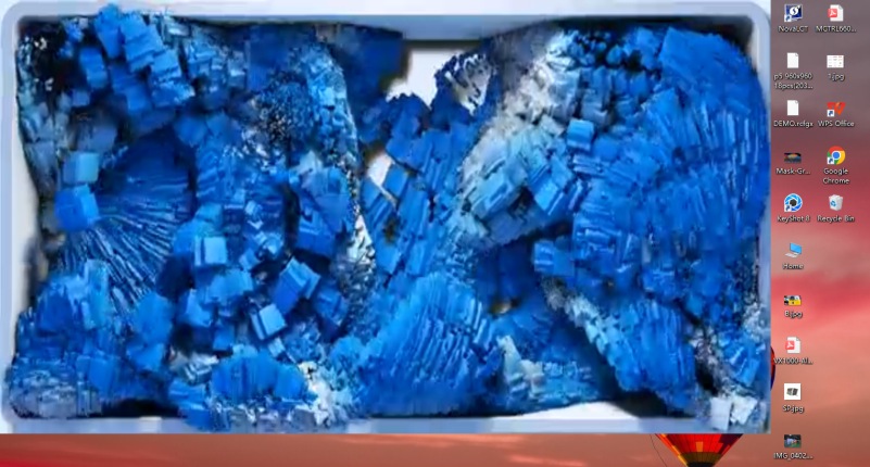
Figure 6-15 Display Effect of the Playback Window on the Computer Desktop
2. Playback Settings in Extended Mode
When the LED display’s resolution is close to or equal to the graphics card’s resolution, the computer’s display interface may be mostly or completely covered, making it impossible to perform other computer-side operations. In this case, the computer’s extended mode can be used for playback to prevent the computer’s display interface from being blocked by the playback window. For Windows 10, for example, simultaneously press the “Windows” key and the “P” key on the keyboard. The working mode options will pop up, and you can select the “Extend” mode. The computer extended mode settings interface is shown in Figure 6-16.
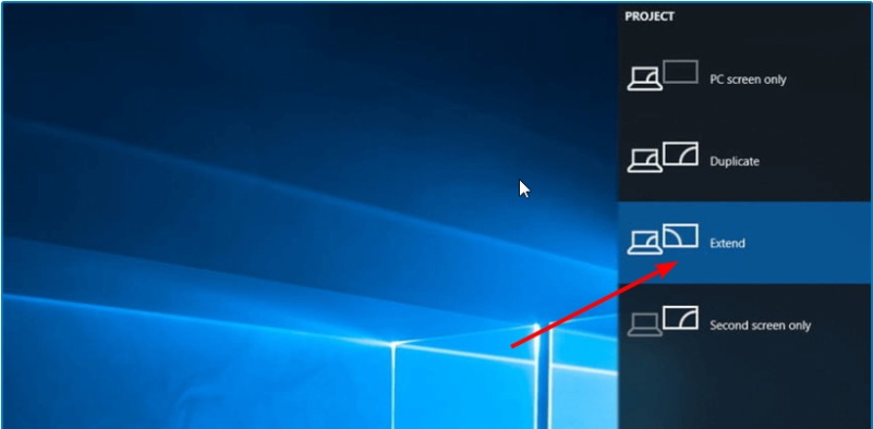
Figure 6-16 Computer Extended Mode Settings Interface
Taking a computer display resolution of as an example, set the coordinate offset in the “Playback Window Setup” dialog box of the Screen Master software, as shown in Figure 6-17. Here, the “X” value should be set to 1920, which means the playback window will be shifted 1920 pixels to the right, and the window size will remain unchanged. At this point, the playback window’s position will disappear from the computer’s desktop, and the LED display will become the computer’s extended desktop.
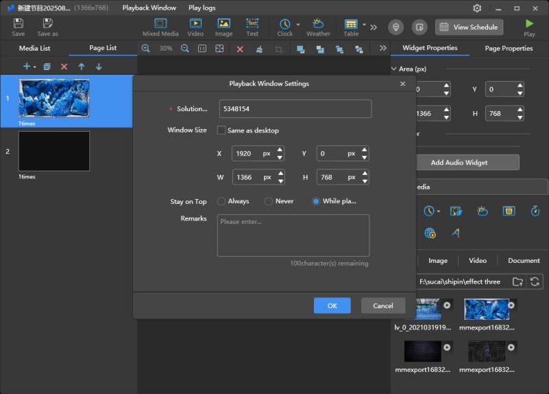
Figure 6-17 Setting Playback Window Size and Starting Position, etc.
To ensure point-to-point display on the LED display, the display scaling value in the computer’s extended mode should be set to 100%, as shown in Figure 6-18.
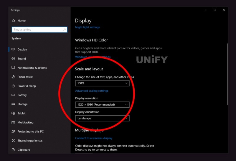
Figure 6-18 Display Scaling Value Set to 100%
After this, you can return to the Screen Master software interface and repeat the program adding and playback operations.
3. Using a Video Processor for Video Source Effects Playback
When the front-end multimedia device cannot output a video source with the same resolution as the LED display, i.e., the front-end output video source resolution is not equal to the LED display’s resolution, a video processor can be used in addition to the Screen Master playback software to ensure that the LED display can completely play the video source content.
One of the most basic functions of a video processor is to scale the video source signal. The video processor’s function to customize the output video source resolution is the video source scaling function. The meaning of scaling is reflected in the ability to magnify a video source with a smaller resolution to the screen resolution, or to shrink a video source with a larger resolution to the screen resolution, thereby achieving complete playback of the video source. Therefore, through a video processor, the resolution of the video source can be scaled to a resolution that matches the LED display. A diagram of the video source scaling effect is shown in Figure 6-19.
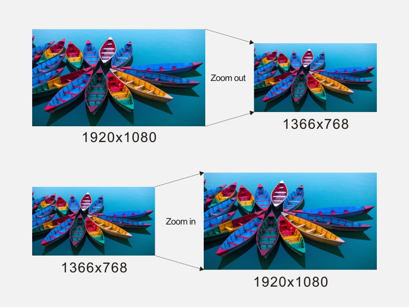
Figure 6-19 Video Source Scaling Effect Diagram
When using a video processor, the computer provides the video source and sends it to the video processor. The video processor processes the video signal and then sends it to the sending card/controller, which ultimately displays the video signal on the LED display. The system structure after adding a video processor is shown in Figure 6-20.
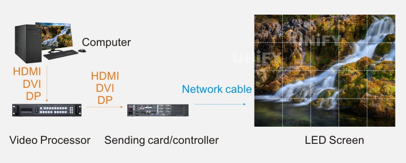
Figure 6-20 System Structure After Adding a Video Processor
Common video processor brands on the market include NovaStar, VDwall, Coleder, VDWALL, and My-Tech. Common video processor brands and models are shown in Table 6-2.
Table 6-2 Common Video Processor Brands and Models
| Video Processor Brand | Video Processor Models |
| NovaStar | N6, N9, VS series |
| VDwall | E2 series, E4 series |
| Coleder | Apollo Pro-V4 series, Mobius series |
| VDWALL | LVP603, LVP605, LVP615, LVP86XX |
| My-Tech | LED-750H, LED-E800, LED-W4000 |
Recommend Products
Indoor LED Screen Case in USA: Elevate Your Church Services
Indoor LED Screen Case in USA: Elevate Your Church Services Home Table of Contents Introduction As churches across the USA

Synchronous Playback for LED Displays
Synchronized Playback for LED Displays Home Table of Contents Synchronized Playback for LED Displays After an LED display is configured,
LED Display Basic Calculations
LED Display Basic Calculation Home Table of Contents Power Consumption Calculation In LED display related engineering projects, the power consumption of