Basic Debugging of LED Displays
- Home
- »
- LED Academy
- »
- Basic Debugging of LED Displays
Table of Contents
Basic Configuration of LED DisplayLED
1. Computer Display Settings
1.1 Copy/Output Settings of Graphics Card
The basic configuration of the LED display is usually set to copy output to ensure that the screen display is consistent with the computer desktop. With the help of desktop icons, the integrity of the screen can be easily judged, and the configuration can be completed efficiently.
(1) Right – click on the blank area of the computer desktop and select the “Display settings” option (as shown in Figure 4 – 1);
(2) Select “Duplicate these displays” or “Extend these displays” to achieve the corresponding output (the “Display settings” interface is as shown in Figure 4 – 2).
(1) Press the “Windows” + “P” keys on the keyboard at the same time;
(2) Select “Duplicate” or “Extend” in the pop – up shortcut menu (the copy setting of the graphics card is as shown in Figure 4 – 3).
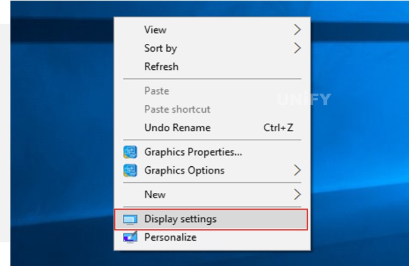
Figure 4-1 “Display settings” option
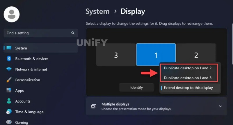
Figure 4-2 “Display settings” interface

Figure 4-3 Graphics card copy setting
1.2 Graphics Card Scaling Settings
Operation Steps:
- Right-click on the blank area of the computer desktop, and select the “Display settings” option from the pop-up shortcut menu.
- In the “Scale and layout” section, select the “100%” option from the drop-down list of “Change the size of text, apps, etc.”, and the option will take effect after exiting, as shown in Figure 4-4.
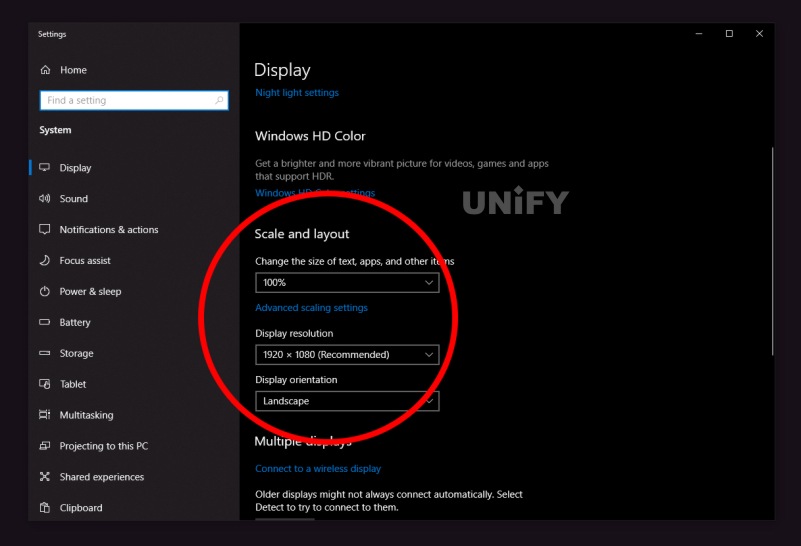
Figure 4-4 “Scale and layout” section
2. Sending Card Settings
2.1 Login to Display Configuration Software
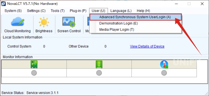
Figure 4-5 NovaLCT software login interface
2.2 Input Source Information Settings
- The basic information of the input video source mainly includes the input source type (HDMI, DP, DVI, etc.), resolution (standard or custom), refresh rate (24Hz, 30Hz, 50Hz, 60Hz, etc.), and input source bit depth (8bit, 10bit, 12bit). After inputting or selecting the basic information, click the “Set” button to complete the setting of the video source, as shown in step “1” in Figure 4-6.
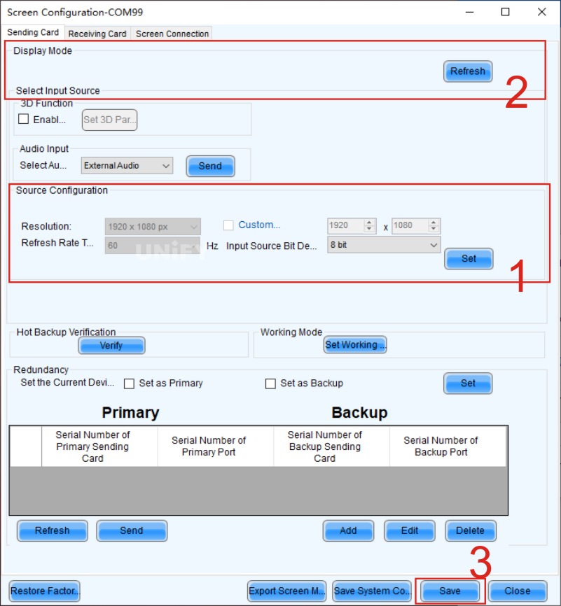
Figure 4-6 Sending card setting interface
- After the setting is completed, click the “Refresh” button in step “2” in Figure 4-6. When the resolution of the sending card is consistent with the output resolution of the graphics card, it can be confirmed as point-to-point output.
- Click the “Solidify” button in step “3” in Figure 4-6 to solidify the parameter settings, so that even if the sending card is powered off and on, the set parameters will not be lost.
3. Receiving Card Settings
3.1 Loading of Receiving Card Configuration File
The operation steps to load the configuration file corresponding to the cabinet into the system are as follows:
- Open the receiving card setting interface, and click the “Load from file” button at the bottom of the interface. The loading of the configuration file is shown in Figure 4-7.
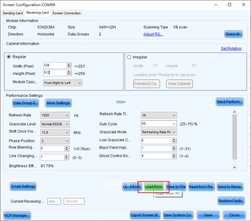
Figure 4-7 Loading of configuration file
- Select the file location in the pop-up path dialog box, as shown in Figure 4-8. Take the file with the type “RCFGX” and the name “DEMO” as an example, select the file and click the “Open” button. At this time, the configuration file parameters of “DEMO” are loaded into the software. After the loading is completed, a prompt “Loading configuration file successfully!” will appear, and click the “OK” button, as shown in Figure 4-9.
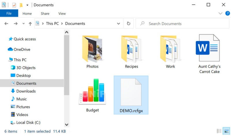
Figure 4-8 Selection of configuration file path
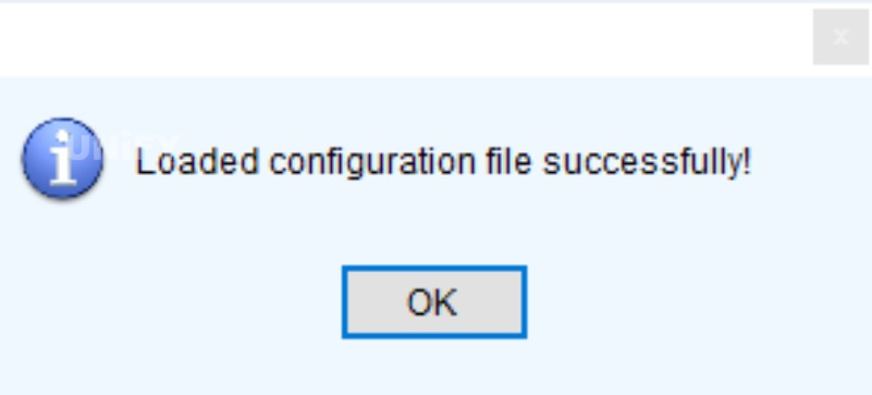
Figure 4-9 Prompt for successful loading of configuration file
- After successfully loading the configuration file, the parameters in the “Light board information”, “Cabinet information”, and “Performance settings” of the receiving card interface will become the parameters in the “DEMO” file.
3.2 Sending of Receiving Card Configuration File
- Click the “Send to receiving card” button on the receiving card setting interface, and a “Send parameters to receiving card” dialog box will pop up at this time, as shown in Figure 4-10.
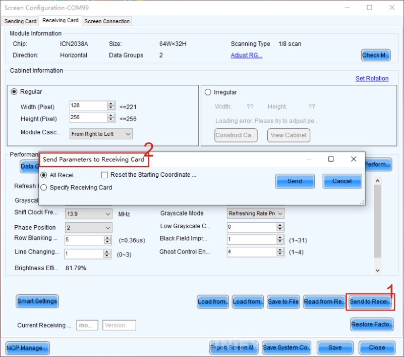
Figure 4-10 Sending to receiving card
- If all receiving cards connected to the control system have the same loaded cabinet resolution and consistent parameters, select the “All receiving cards” radio button, and then click the “Send” button to broadcast the parameters to all connected receiving cards. If there are cabinets of different specifications, select the “Designated receiving cards” radio button, and then select the designated receiving card position from the topology diagram for sending.
- After the receiving cards are correctly set, the screen of the display will be displayed repeatedly in units of receiving cards, and the display range is the size of the area loaded by the receiving card in the upper left corner of the video source. Figure 4-11 shows the display of 8 receiving cards’ loaded areas. It should be emphasized here that in the control system, a single receiving card represents a single cabinet, but in practice, there may be a physical cabinet containing two receiving cards, which should be regarded as two cabinets in the control system.
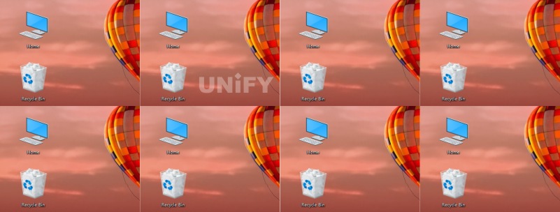
Figure 4-11 Display of 8 receiving cards’ loaded areas
3.3 Solidification of Receiving Card Configuration File
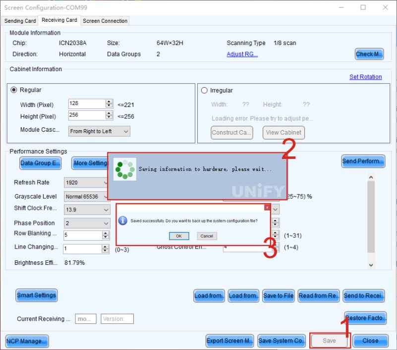
Figure 4-12 Solidification of receiving card configuration file
3.4 Reading Back of Receiving Card Configuration File
- When there is no configuration file on site, the parameters can be read back from the normally displayed cabinet and saved to a file, as shown in Figure 4-13.
- When part of the cabinet display is abnormal, the configuration file can be read back from other receiving cards with the same configuration and normal display, and then sent.
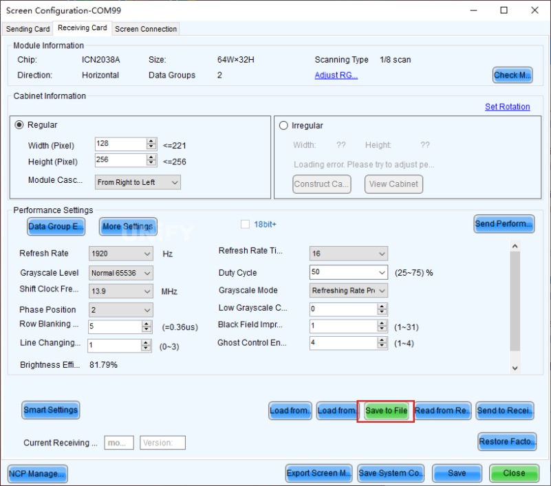
Figure 4-13 Reading configuration file from receiving card
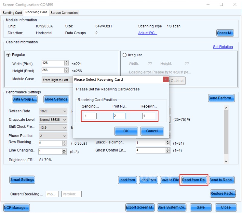
Figure 4-14 Reading back of receiving card configuration file
4.Receiving Card Settings
4.1 Regular Operation Steps
- The “Number of displays” is 1 by default, click the “Configure” button. “Number of displays” refers to the number of displays in the control system, and there is usually only 1 display in the basic configuration.
- Fill in the corresponding numbers in the value boxes after “Number of receiving card columns” and “Number of receiving card rows”. As shown in Figure 4-15, set it to 4 columns and 2 rows of receiving cards. After entering the number of rows and columns of the receiving cards, click the “Reset all” button or press the “Enter” key.
- In the “Sending card number” section, you can see the number of sending cards connected under the current control system. Select the sending card number corresponding to the target screen, and similarly, you need to select the network port number corresponding to the output of the sending card.
- Set the width and height of the receiving card in the “Receiving card size” section, that is, the size of the area loaded by the receiving card. The relevant parameters can be obtained from the “Cabinet information” section in the receiving card setting interface in Section 3.1.3.
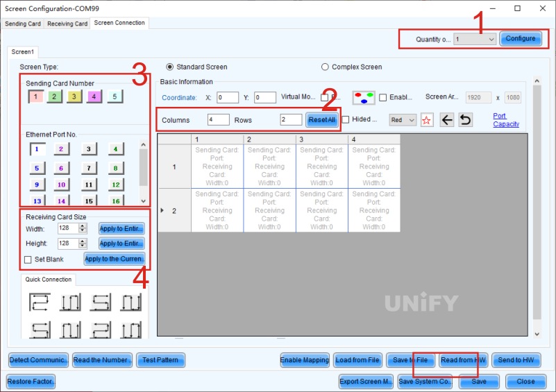
Figure 4-15 Display connection
After completing the above settings, you can start the display connection operation. The sending of display connection parameters is shown in Figure 4-16.
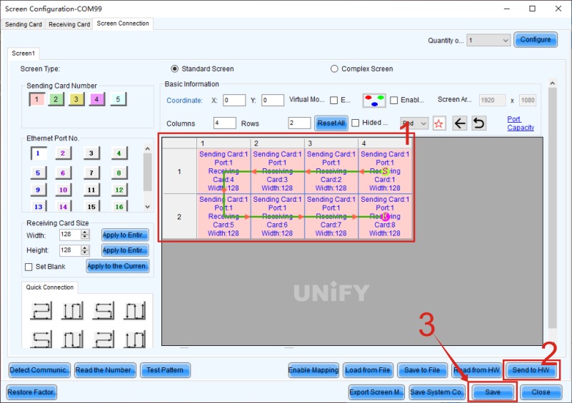
Figure 4-16 Sending of display connection parameters
- Complete the display connection by dragging the mouse or using the keyboard direction keys. When connecting the display, you need to observe the network cable connection direction from the front of the screen (front view), then find the correct starting point on the topology diagram, and start the connection.
- After drawing the display connection topology diagram, click the “Send to hardware” button.
- After sending the screen connection information to the hardware, click the “Solidify” button, and the display connection information will be successfully saved in the hardware.

Figure 4-17 Completed display connection
4.2 Mapping Function
- Scenario 1: When installing and debugging a new screen on the engineering site, the Mapping function can be used to judge the correct network cable connection mode without connecting a video source device, making on-site screen connection more convenient and fast.
- Scenario 2: When the display screen is not connected normally and there is disordered and misplaced display, the Mapping function can be used to verify whether the on-site network cable is inserted incorrectly, or whether there is a discrepancy between the software display connection setting and the physical network cable connection.
- Open the “Display connection” tab, and click the “Enable Mapping” button at the bottom, as shown in Figure 4-18.
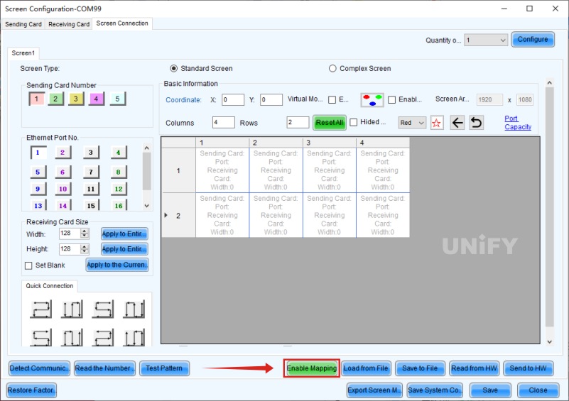
Figure 4-18 Enabling Mapping function
- After enabling the Mapping function, each cabinet of the LED display will display the physical connection information of the receiving card. The demonstration of the Mapping function is shown in Figure 4-19. Among them, “S” refers to the sending card, that is, the number of the sending card device under the current communication serial port; “P” refers to Port, that is, the output network port; “# number” indicates the number of the receiving card under the network port. Taking the display shown in Figure 4-19 as an example, the display is loaded through sending card 1, using 1 network port, namely “network port 1”, and there are 8 receiving cards connected. The connection sequence starts from the upper right corner, connects in series to the 4th receiving card to the left, then connects to the receiving cards in the second row, and then completes the network cable connection to the right in turn.
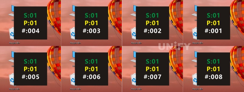
Figure 4-19 Demonstration of Mapping function
- Perform the correct display connection operation again according to the Mapping information, as shown in Figure 4-20.
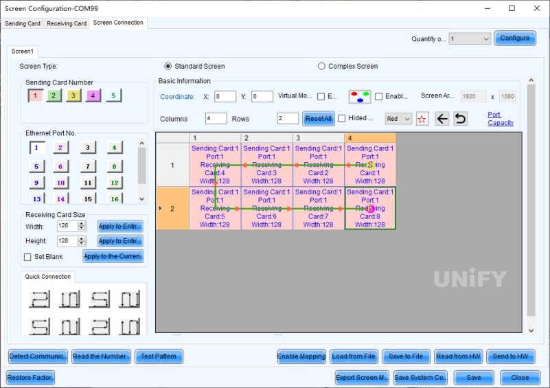
Figure 4-20 Correct display connection
- Resend and solidify, and the LED display can realize the complete display of the picture as shown in Figure 4-21.
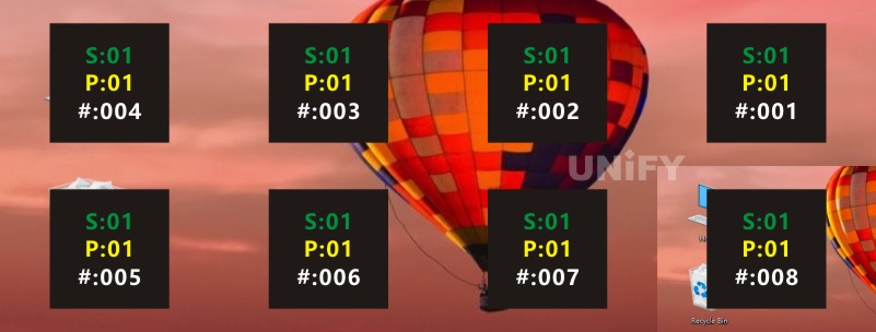
Figure 4-21 Complete display of the picture
4.3 Coordinate Offset
- In the “Basic information” section of the “Display connection” tab, you can set the X and Y coordinate values to achieve coordinate offset. In the example shown in Figure 4-22, both the X and Y values of the connection diagram are set to 200, that is, all are offset by 200 pixels.
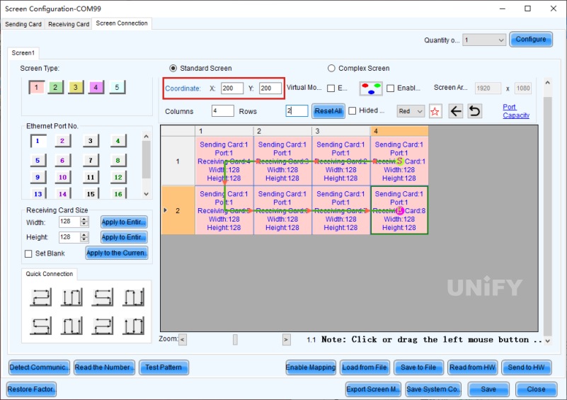
Figure 4-22 Coordinate offset setting
- After sending the parameter information to the hardware and solidifying it, the actual display picture of the LED display is as shown in Figure 4-23, and the picture will start to be displayed from the coordinate (200, 200) of the desktop.

Figure 4-23 Display picture after coordinate offset
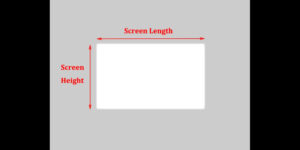
4.4 Screen Space Reservation

Figure 4-24 Hollow design of the screen
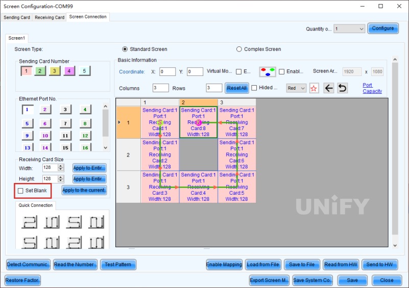
Figure 4-25 Screen space reservation setting
4.5 Rectangular Loading Principle
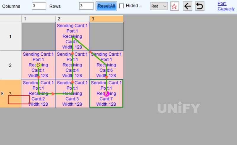
Figure 4-26 “Rectangular loading” rule
System Backup Settings
1. Sending Card Cascading Backup
1.1 Cascading with 5Pin Cascade Cable
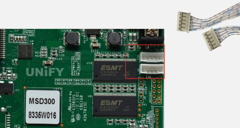
Figure 4-27 Cascading with 5Pin cascade cable
1.2 Cascading with Aviation Plug Cascade Cable
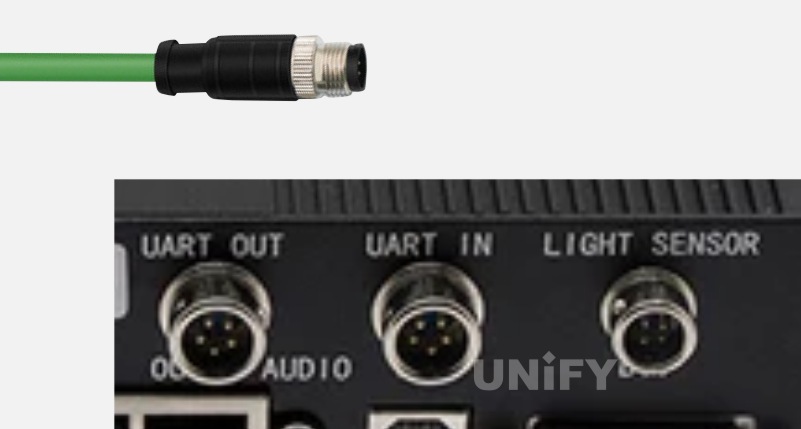
Figure 4-28 Cascading with aviation plug cascade cable
1.3 Cascading with Network Cable
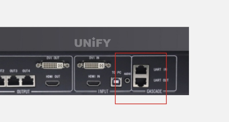
Figure 4-29 Cascading with network cable
1.4 Cascading with USB Cable
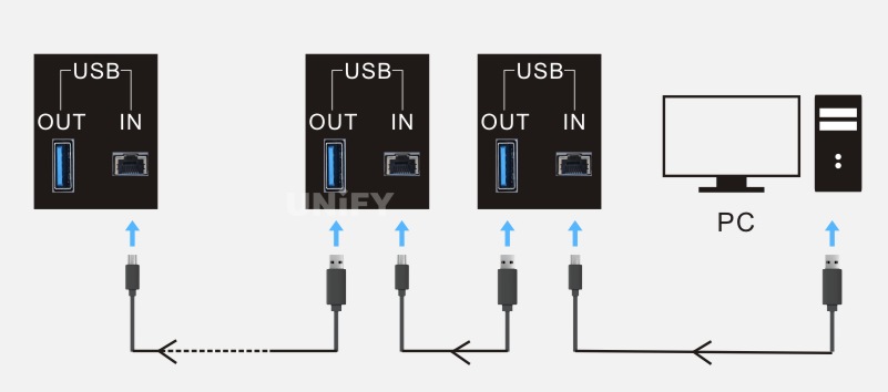
Figure 4-30 Cascading with USB cable
It should be noted that only sending cards of the same model can be cascaded, and sending cards of different models cannot be cascaded. After the sending cards are cascaded, you can click “View Device Details” on the main interface of NovaLCT software, and check whether the cascading is successful in the pop-up “Total Number of Device Types” window.
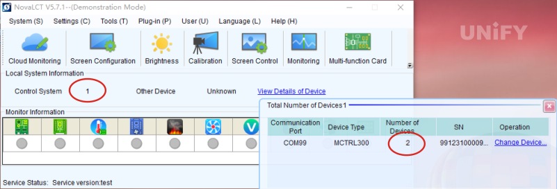
Figure 4-31 Checking cascading success
When multiple devices appear under the same communication port, it indicates that the cascading is successful.
2. Backup Settings Between Different Network Ports of the Same Sending Card
2.1 System Architecture
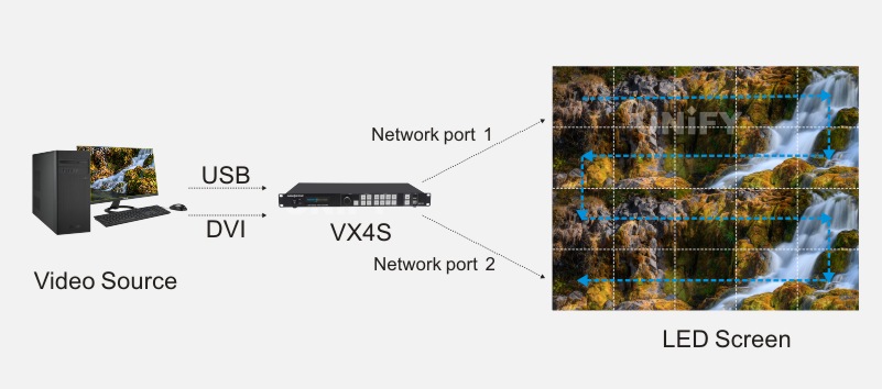
Figure 4-32 System architecture of backup between different network ports of the same sending card
As shown in Figure 4-32, the screen is carried by network port 1 of the sending card, and network port 2 is used as the backup of network port 1. Therefore, in hardware connection, a network cable is needed to connect network port 2 of the sending card to the last network port of the last receiving card of the display to form a closed loop in the entire system.
2.2 Software Settings
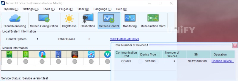
Figure 4-33 Checking the number of control systems and sending cards
(2) According to the actual wiring method, connect the screen in NovaLCT software to make the screen display normally.
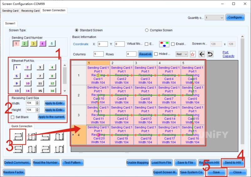
Figure 4-34 Performing screen connection
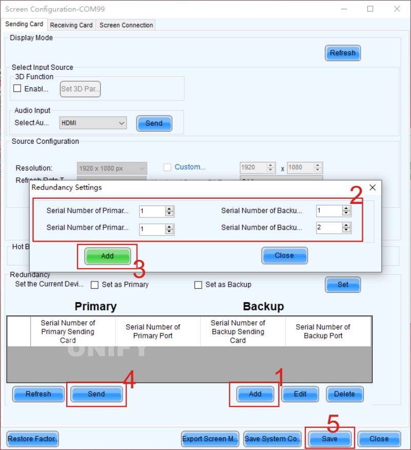
Figure 4-35 Redundant backup setting
① In the “Sending Card” tab interface, click the “Add” button below to open the “Redundant Setting” dialog box.
② Add redundant backup information: Set “Master Output Port Number” to 1 and “Backup Output Port Number” to 2, indicating that network port 2 is the backup of network port 1.
③ Click the “Add” button to confirm that all network port settings are correct.
④ Click the “Send” button to send all settings to the hardware, i.e., the sending card.
⑤ Click the “Solidify” button to solidify the redundant backup information into the sending card, and the redundant backup setting is completed.
3. Backup Settings Between Cascaded Sending Cards
3.1 System Architecture
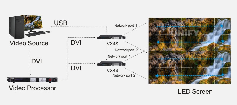
Figure 4-36 System architecture of backup between cascaded sending cards
3.2 Software Settings
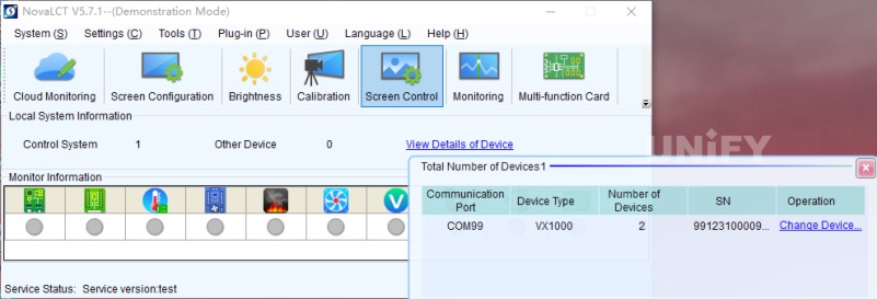
Figure 4-37 Single system + two sending cardsFigure 4-37 Single system + two sending cards
(2) According to the actual wiring method, use sending card 1 to connect the screen in NovaLCT software to make the screen display normally.
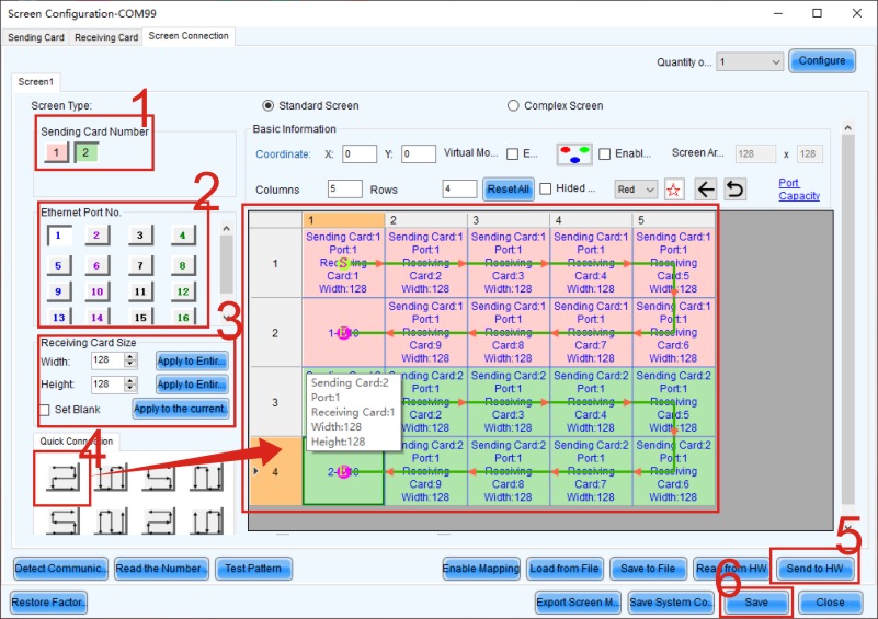
Figure 4-38 Using sending card 1 for screen connection
If the screen connection is incorrect, the backup setting cannot work normally.
(3) Enter the “Sending Card” tab interface to set backup.
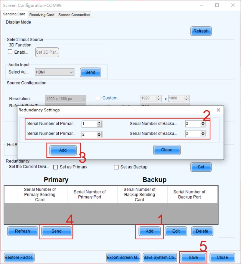
Figure 4-39 “Sending Card” tab interface
① In the “Sending Card” tab interface, click the “Add” button below to open the “Redundant Setting” dialog box.
② Add the redundant backup sequence: Set “Master Sending Card Number” to 1, “Backup Sending Card Number” to 2, “Master Output Port Number” to 2, and “Backup Output Port Number” to 2, indicating that network port 1 of the second sending card is the backup of network port 1 of the first sending card.
③ Click the “Add” button to confirm that all network port settings are correct. If there are more network port correspondences, they can be added in the same way.
④ Click the “Send” button to send all backup settings to the hardware.
⑤ Finally, click the “Solidify” button to solidify the redundant backup information into the sending card, and the backup setting is completed.
4. Backup Settings Between Non-Cascaded Sending Cards
4.1 System Architecture
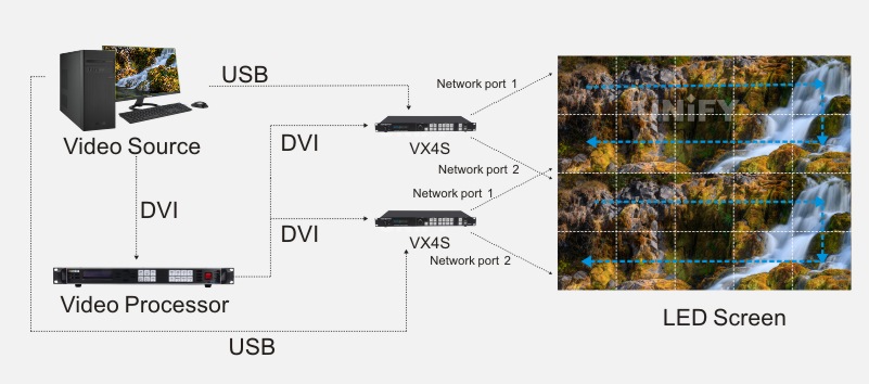
Figure 4-40 System architecture of backup between non-cascaded sending cards
4.2 Software Settings
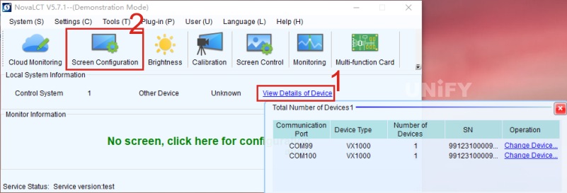
Figure 4-41 Two control systems + two sending cards
(2) When clicking the “Display Configuration” button on the main interface of NovaLCT software, a dialog box will pop up.
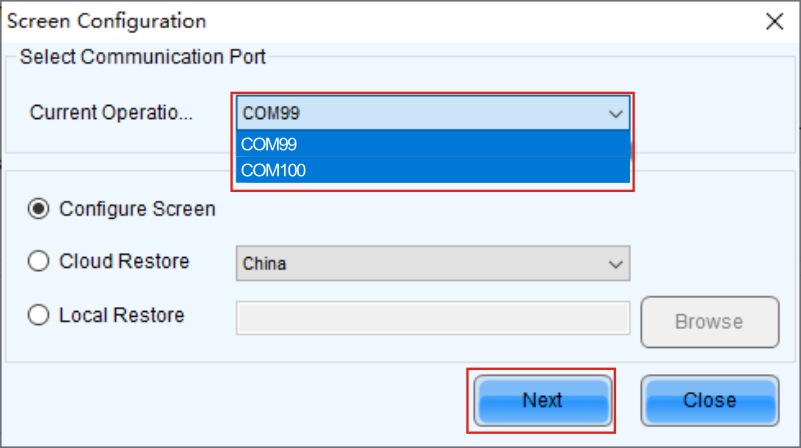
Figure 4-42 Master device setting
In this example, select the communication port “USB@Port_#0002.Hub_#0002” as the master device. According to the actual wiring method of the display, connect the display in NovaLCT software to make the screen display normally.
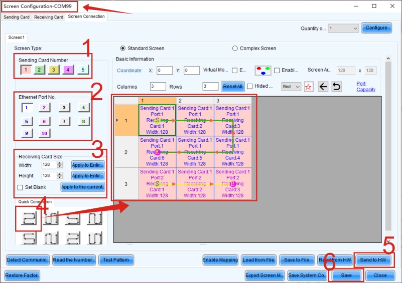
Figure 4-43 Setting the display connection of the master device
(3) Open the “Sending Card” tab interface for backup settings. In this setting, there is no need to add the corresponding relationship of backup. Just check the “Set as Master” checkbox in the “Redundancy” section at the bottom of the interface, and then solidify all settings.
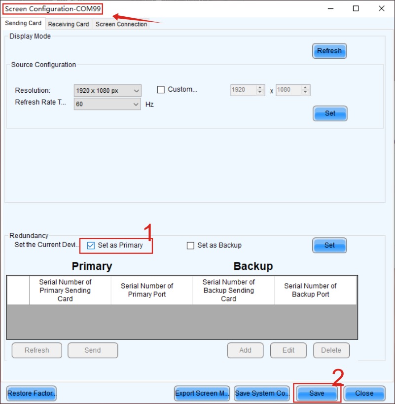
Figure 4-44 Master device setting
(4) Return to the display configuration page and select another communication port for configuration, i.e., the “USB@Port_#0003.Hub_#0002” communication port. The sending card under this communication port is the backup device. At this time, it is necessary to perform the same display connection operation as the master device.
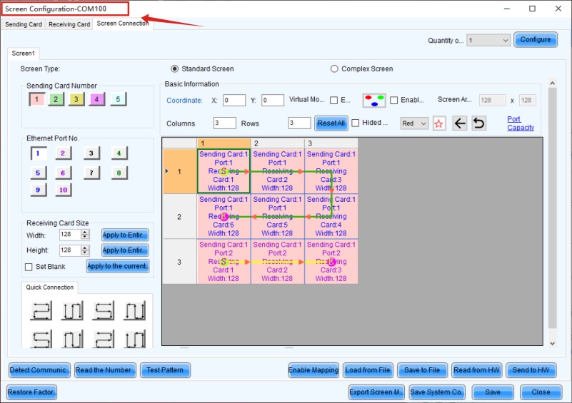
Figure 4-45 Setting the display connection of the backup device
(5) Enter the “Sending Card” tab interface again for backup settings. At this time, just check the “Set as Backup” checkbox, and then solidify all settings.
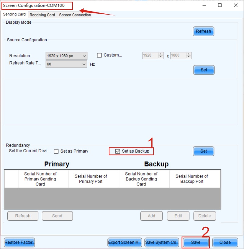
Figure 4-46 Backup device setting
4.3 Hardware Setting Backup
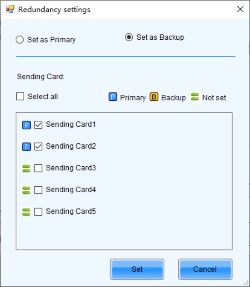
Figure 4-47 Hardware setting backup
On the front panels of the two sending cards, select “Advanced Settings” → “Redundant Settings” → “Set as Master”/”Set as Backup” in sequence. The operation logic of the front panel of different models of sending cards is roughly the same. For specific operations, please refer to the user manual of the sending card of that model.
Recommend Products

Indoor LED Screen Case in USA: Elevate Your Church Services
Indoor LED Screen Case in USA: Elevate Your Church Services Home Table of Contents Introduction As churches across the USA seek to engage congregations with richer audio-visual experiences, the adoption of LED display technology has surged. Indoor LED screens are now a central feature in worship spaces, transforming the way messages and media are presented.

Synchronous Playback for LED Displays
Synchronized Playback for LED Displays Home Table of Contents Synchronized Playback for LED Displays After an LED display is configured, it needs to play content from a front-end input. When this content needs to be played in real-time, it is called synchronized playback for an LED display. Synchronized playback refers to the LED display playing
LED Display Basic Calculations
LED Display Basic Calculation Home Table of Contents Power Consumption Calculation In LED display related engineering projects, the power consumption of the screen power supply is a crucial parameter for evaluating screen performance and is closely tied to the safety of project construction. Incorrect calculation of the power consumption of an LED display in the early