The basic structure of LED display
- Home
- »
- LED Academy
- »
- The basic structure of LED display
Table of Contents
The Composition of LED DisplaysLED
With the rapid development of LED display technology, LED displays are being used more and more widely in various industries and are becoming increasingly common in daily life. Their brilliant display effects and massive display sizes bring a great visual shock to the viewer. So, what exactly is the production, transportation, and installation process for such a display screen?
In fact, the large LED displays we see are all assembled from LED cabinets or even smaller units of LED modules. This method can significantly reduce the costs of the entire process from production to installation of the LED display, effectively improve the efficiency of each stage, enhance the flexibility of using the LED display, and allow for assembly into different sizes and shapes according to different usage scenarios and customer needs. This is an advantage that traditional display media cannot compare with. The installation of an outdoor LED display is shown in Figure 1-1. The display effect of an LED display is shown in Figure 1-2.
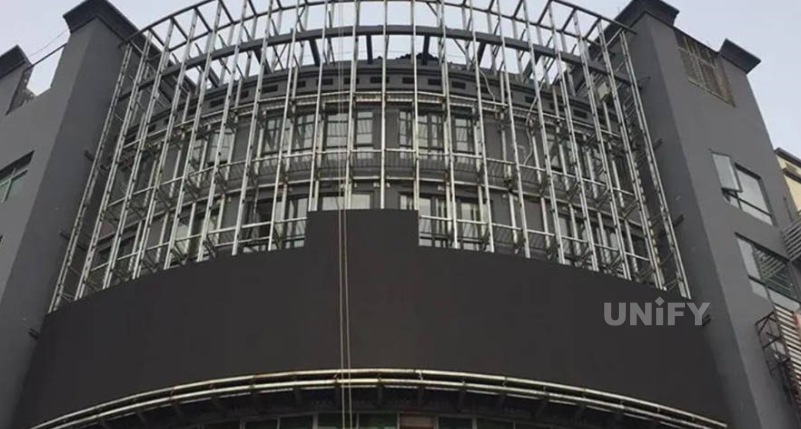
Figure 1-1 Installation of an outdoor LED display

Figure 1-2 Display effect of an LED display
1. LED Module
LED module , also known as an LED lamp board, is the smallest detachable component of an LED display at the application level. An LED module is generally composed of LED lamp beads, signal input/output interfaces, chips, a plastic kit, a PCB substrate, and a power input interface. The basic composition of an LED module is shown in Figure 1-3.
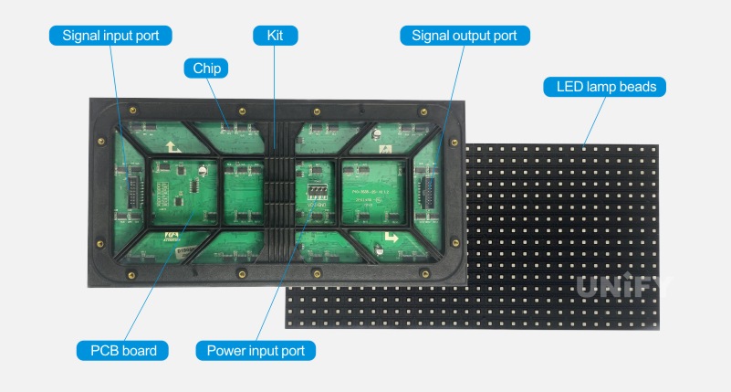
Figure 1-3 Basic composition of an LED module
LED lamp beads. These are light-emitting diodes, which are the display light source for the LED screen.
PCB substrate. Acting as a hub platform for signal transmission, its role is to connect the control chips, LED lamp beads, signal input/output interfaces, and power input interface via PCB circuits. After the components are soldered, the PCB substrate becomes a unit board that can be lit up, which is commonly known as an LED module (lamp board). The PCB substrate is shown in Figure 1-4.
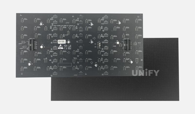
Figure 1-4 PCB Substrate
Plastic Kit. Usually made of plastic material, it is mainly used for fixing and protecting the LED module. It can fix the LED module to the LED cabinet structure or directly to a steel structure for assembling a large LED display screen. However, not all LED modules need to be fixed with a kit; many LED modules integrate bolts for fixing, so these LED modules do not require a kit.
Chips. Their main role is to control the on/off state and light intensity of the LED lamp beads by receiving control signals output from the receiving card’s control system. By precisely controlling the tens of thousands of pixel points on the LED display, the desired image can be displayed. A conventional LED module generally includes power amplifier chips, decoder chips (including CMOS power transistors), and driver chips.
Power amplifier chip: A commonly used power amplifier chip is the 74HC245 power driver chip. Its main functions are signal driving and signal isolation (for multiple data sets in an LED module, one signal path is generally connected in parallel to multiple input channels of a 74HC245, and multiple output channels independently output to the control chips for different data)
Decoder chip: A common method uses a 74HC138+4953 combination. The decoding signal controls the 74HC138 channel output and the 4953 power transistor’s conduction, thereby connecting the positive pole of a row or column of LED lamp beads in the module to the power supply. With the development of the LED industry, many decoder-and-driver-in-one chips specifically for LED displays have appeared, such as RT5958, DM7258, ICND2013, ICND2018, etc.
Signal input/output interface. This connects the control signals output from the control system to the LED module via a ribbon cable from the receiving card, and also connects signals between LED modules via ribbon cables for display control of the modules.
Power input interface. This is the input interface that supplies power to the LED module.
2. LED Cabinet
The LED cabinet is generally the basic component unit of an LED display, formed by arranging LED modules in a certain order. The overall composition of an LED cabinet is shown in Figure 1-5.
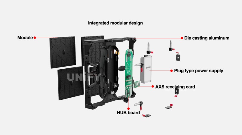
Figure 1-5 Overall composition of an LED cabinet
LED cabinet structure. The material is generally iron, die-cast aluminum, carbon fiber, etc.. It is mainly used to fix the internal components of the LED cabinet to facilitate the assembly of the LED display, and it also plays a good protective role.
Switching power supply. Generally, LED displays require a DC low-voltage power supply, with commonly used DC voltages ranging from 2.8V to 5V. The standard mains electricity in China is 220V/50Hz. There are many different mains electricity standards used abroad. To improve the applicability of LED displays in different regions, the switching power supplies used in the LED industry generally have an input voltage of AC 100-240V and 50/60Hz, with rated output powers mostly concentrated between 150-400W.
Receiving card. This is the control hub for the LED cabinet’s display. It can output different control signals according to the different driver chips and circuits of the LED cabinet, thereby controlling the normal display of the cabinet.
Adapter board. It can rearrange and combine the data control signals output by the receiving card according to the definition of the LED module’s signal input interface, and transmit the signals to the LED module through ribbon cables or direct interface connections. Its size and shape are determined by the internal structure of the LED cabinet.
LED Display Control System
The display principle of an LED display control system is as follows: a device with video output capability outputs a video source signal in a specific format. The signal is transmitted to the LED controller via a video cable, converted into an RGB signal by the LED controller, and then the RGB signal is transmitted to the receiving card via a network cable or fiber optic cable. The receiving card converts the RGB signal into a digital logic signal that the driver chip can recognize, which is then transmitted to the LED display via a ribbon cable or PCB circuit to achieve the final display effect. The control system architecture is shown in Figure 2-1.
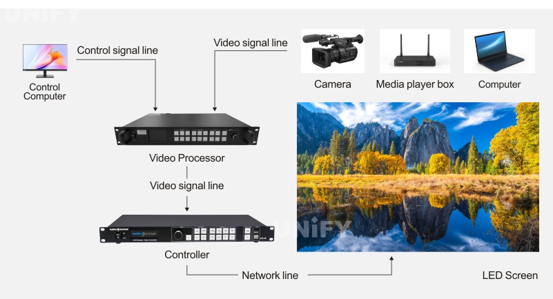
Figure 2-1 Control system architecture diagram
1. Video Playback Devices and Control Computer
For the LED display synchronous control system, the content displayed on the LED display needs to provide synchronous video input. Generally, the devices with video source output functions include computers, media players, DVDs, TV set-top boxes, cameras, etc. The current mainstream video interfaces include DVI, VGA, DP, HDMI, SDI, CVBS, etc. Common LED control systems have corresponding upper computer control software, and the general control methods include RS232, USB, TCP/IP, etc. Therefore, at the front end of the entire system link, there is generally a control computer with an operating system as the control terminal.
2. LED Controllers and LED Video Processors
(1) LED Controller
In the industry, the LED controller is also known as a sending card, standalone master controller, etc.. The term “sending card” appearing in the main text or software images of this book refers to the LED controller unless otherwise specified.
The main function of the LED controller is to receive the video source signal provided by a front-end video source device or computer, and process the received video signal into a differential signal that can be transmitted via a network cable. It then transmits this signal to the receiving card through a network port and cable, which is finally displayed on the LED screen.
The specific functions of an LED controller are mainly the following three.
Receiving the video source signal and parsing it into a signal that the controller can process, using a decoding chip or FPGA.
Splitting each frame of the processed image according to the number of network ports used and the topology map, dividing it into images for the corresponding network port areas.
Sending proprietary protocol packets such as field packets, row packets, command packets, and audio packets to the receiving card.
The interfaces on an LED controller mainly include video input interfaces, control input interfaces, and output interfaces. Video input interfaces include DVI, HDMI, SDI, DP, etc.. Control input interfaces include RS232, TCP/IP, USB, etc. Output interfaces are generally divided into video output interfaces, Gigabit output network ports, and fiber optic output ports.
Video Output Interface. In control systems, common types of video output interfaces are OUT, LOOP, and Monitor, and there are certain differences between them. Taking DVI as an example, the content output from the DVI OUT interface has been processed by the LED controller, and the displayed image is related to the display screen parameters configured in the controller. If the controller is configured with screen information of 512×512 resolution, then the DVI OUT output image will only be 512×512 pixels in size. When an LED controller is connected to a DVI input source, for the DVI LOOP interface, LOOP means signal loop-out. As the name suggests, DVI LOOP will output this DVI source again without any processing. That is, the information from DVI LOOP output is the same as the original DVI input. The Monitor output, on the other hand, connects the signal output by the LED controller to an external monitor for monitoring, and it typically supports a resolution of 1080p.
Gigabit Output Network Port. It is usually used for connecting between the sending card and the receiving card to transmit image information and control commands.
Fiber Optic Output Port. Its function is the same as the network port’s, suitable for long-distance transmission. However, the signal conversion between the fiber optic port and the network port must be considered, and it usually needs to be used in conjunction with photoelectric conversion equipment.
(2) LED Video Processor
The LED video processor is a non-essential part of the LED display control system link; without a video processor, the LED display can still show images. Its role is to make the images displayed on the LED screen more flexible and rich. It is a witness and a landmark device for the entire process of the birth, growth, and maturation of LED displays, playing a significant role in the traditional LED control system link. Its functions mainly include the following aspects.
Image Cropping. Crop any part of a complete image and scale it up or down for display in any area of the LED screen.
Image Scaling. Scale the input video source image up or down for display on the LED screen, which is suitable for situations where the resolution of the front-end input source does not match the resolution of the LED display. Scaling can achieve a full-screen display effect.
Signal Conversion and Switching. This function can complete format conversions between many signals. For example, if the input source is an HDMI signal, the video processing device can convert it to a DVI signal for output. It can also manage various signals when multiple signals are connected, allowing for flexible and rapid switching between different signals.
Image Quality Enhancement. The pixel pitch of LED displays themselves is much larger than other flat-panel display media, which places strict requirements on image processing technology, especially on image enhancement technology. A high-quality LED video processor can use advanced algorithms to touch up signals with poor image quality, performing a series of processes such as de-interlacing, edge sharpening, and motion compensation to enhance image details and improve picture quality.
LED Display Splicing. The pixel pitch of LED displays is getting smaller and smaller, and their physical dimensions are becoming increasingly massive, which makes the physical resolution of LED display screens huge. A single LED sending card cannot drive such a load, requiring multiple devices. At this point, how to splice the images from the load areas of two LED sending cards for a complete display is the job of the video processor, which is its splicing function.
Multi-window (Picture) Processing. In many special scenarios, a single display needs to show multiple images from the same or different signals. A video processor with multi-window processing capabilities can flexibly meet the display requirements for multiple images.
3. Video Cables
Video cables are mainly used to connect video source devices and video processors, as well as video processors and sending cards, and to transmit image information. Commonly used cables include DVI, HDMI, DVI to HDMI, DP, HDMI to DP, and VGA cables.
4. Gigabit Network Cables and Fiber Optic Cables
Gigabit network cables and fiber optic cables are mainly used for data transmission between the LED sending card and the receiving card. The transmission medium varies with the transmission distance. Common transmission methods include standard Gigabit network cables and fiber optic cable transmission (which requires a photoelectric converter to convert electrical signals into optical signals for transmission).
Gigabit Network Cable. These are divided into Category 5, Category 5e, Category 6, and Category 6a network cables, used for connecting the sending card and receiving card to transmit image information and control commands. The connector used is the RJ45 crystal head. The entire LED display industry uses the standard T568B wiring sequence for network cables. According to the ANSI/TIA/EIA cabling regulations, the maximum transmission distance is 100m.
Fiber Optic Cable. Generally divided into single-mode and multi-mode fiber. The transmission distance of single-mode fiber is 15km, while the transmission distance of multi-mode fiber is 300m. The commonly used interface in LED control systems is the LC interface, used for transmitting image information and control commands between the sending card and the receiving card. It is also used when the distance between the LED controller and the receiving card is too far for network cable transmission to suffice.
5. Receiving Card
The receiving card is an indispensable key component in the control system. It is the core control part on the LED display side, and its function is to convert the RGB signal transmitted from the sending card into a logical digital signal that the LED display’s driver circuit can recognize, thereby controlling the image display of the LED screen. It should be noted that sending cards and receiving cards from different manufacturers cannot be mixed.
Common Controller Products in Control Systems
The main suppliers of LED display control systems on the market include Xi’an NovaStar Technology Co., Ltd. (NovaStar), Shenzhen Linsn Technology Development Co., Ltd. (hereinafter referred to as Linsn Technology), Shenzhen Mooncell Electronics Co., Ltd., Colorlight Cloud Tech Co., Ltd. (hereinafter referred to as Colorlight), and Brompton Technology Ltd. (hereinafter referred to as Brompton Technology). Currently, Xi’an NovaStar Technology Co., Ltd. (hereinafter referred to as NovaStar) holds the largest market share in the control system market. Therefore, this section will mainly use NovaStar’s controller products as examples for explanation.
1. Controller Hardware Introduction
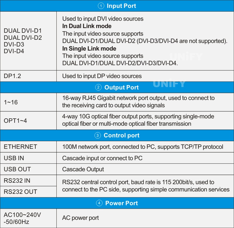
The following uses NovaStar’s MCTRL1600 controller as an example to introduce the hardware composition of a controller. The front panel structure of the MCTRL1600 is shown in Figure 3-1, and the functions of the front panel and buttons are described in Table 3-1. The rear panel structure of the MCTRL1600 is shown in Figure 3-2, and the functions of the rear panel are described in Table 3-2.
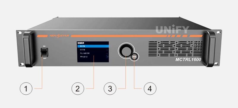
Figure 3-1 MCTRL1600 front panel structure
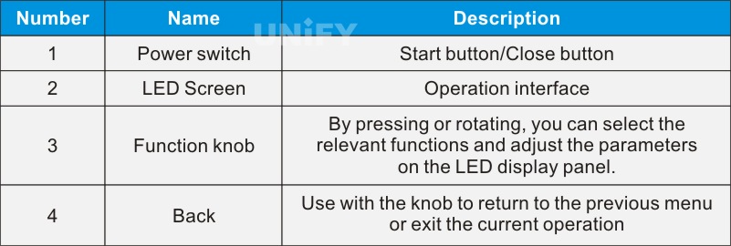
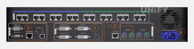
Figure 3-2 MCTRL1600 rear panel structure图 3 – 2 MCTRL1600 后面板结构
2. The Development History of LED Controllers
With the overall development of the LED display industry, related upstream and downstream manufacturers are also constantly evolving their products to meet the ever-changing market demands and provide customers with a better user experience. The LED controller has mainly gone through the following development stages.
(1) From Bare Control Cards to Cased Controllers
When sending cards first became widely used in the LED display industry, they appeared in the form of bare cards. At that time, the control cards were not equipped with a power module and were usually installed in the reserved slots of a desktop computer’s graphics card or a video processor’s reserved slots. They were powered by the desktop computer or video processor, which also provided the signal source. The advantage of this was that it was lightweight and saved space.
As the application scenarios for LED displays became more widespread, the video source was no longer just a single desktop computer or a video processor with reserved card slots; it could also be a laptop. In this case, the separate power supply for the control card had to be considered. For example, in some outdoor scenarios where the control card needs to be placed inside the LED display cabinet, issues such as moisture resistance, dust resistance, and water resistance must be taken into account. From a safety perspective, bare card controllers posed a security risk, and this structure could no longer meet the application needs of LED displays. Thus, bare card controllers transitioned to cased controllers, also known as standalone master control devices, such as NovaStar’s MSD300 (bare card controller) to the MCTRL300 (standalone controller), as shown in Figures 3-3 and 3-4.
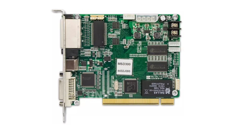
Figure 3-3 MSD300 (bare card controller)
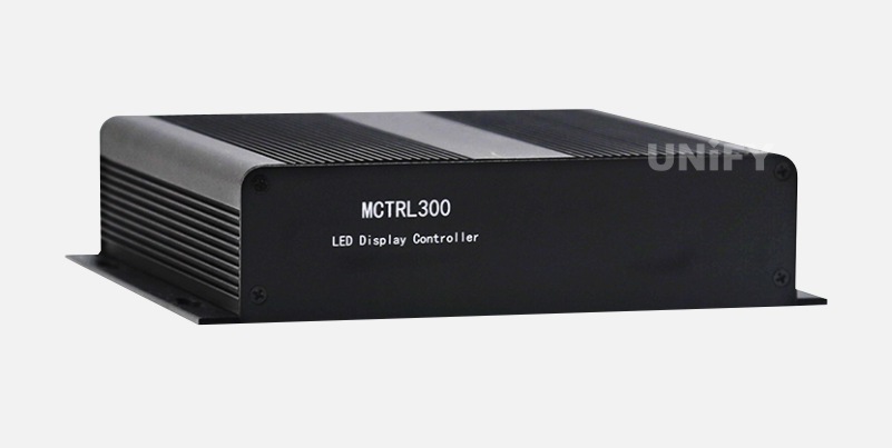
Figure 3-4 MCTRL300 (standalone controller)
(2) From Dual-Port to Multi-Port Controllers
When LED displays were first applied in the display industry, they were mostly used in outdoor settings. The size of the LED lamp beads was relatively large, the pixel pitch of the screens was also large, and the price per unit area of LED displays was high. Coupled with the constraints of input source interface resolutions at the time, the actual pixel resolution of an LED display was not very high, usually within 1080p resolution. In the control system, a single controller’s single network port had a load capacity of about 650,000 pixels. An MCTRL300 had two network ports, with a load capacity of 1.3 million pixels, which could basically meet the loading demands of LED displays at that time.
With the development of LED lamp bead technology, the size of the beads became smaller and smaller, and the pixel pitch of displays further shrank. The application of LED displays gradually moved from outdoors to indoors. At the same time, the video industry was also constantly developing, the resolution of video source interfaces gradually increased, and the price per unit area of LED displays gradually decreased. This led to an increasing pixel density per unit area in actual applications, and screen resolutions became larger and larger, with 1080p displays becoming commonplace. At this point, dual-port controllers could no longer meet the development needs of the industry. Thus, a larger load capacity and more network ports became the call of the market, and the load capacity of LED controllers increased accordingly. For example, NovaStar’s MCTRL600 was upgraded to 4 network ports, allowing a single device to drive a large 1080p resolution screen. The appearance of the MCTRL600 product is shown in Figure 3-5. Later, there was the MCTRLR5 with 8 network ports, supporting a large screen with 4K×1K resolution. Even later, the MCTRL1600 with 16 network ports appeared, allowing a single device to drive a large 4K×2K resolution screen.

Figure 2-11 MCTRL600 product appearance
(3) From Software Control to Front Panel Operation
To configure a display screen in an LED control system, we need to install host computer control software on a computer and then connect to the controller via a USB serial cable to perform configuration operations. All operations must be done through a computer, which requires carrying a computer for on-site configuration, which is not very convenient. Furthermore, it requires users to have a certain understanding and mastery of computer operations and industry software. However, in reality, many users are not professionals in the LED display industry and cannot perform some professional LED display operations, leading to high learning costs for many end-users.
To solve the above problems, and to improve the visualization of operations and more intuitively display the current controller’s input source, output network ports, and operating status, control system manufacturers added an LCD panel and a knob to the LED controller. Through the controller’s LCD panel and knob, quick configuration of the LED display, brightness control, etc., can be achieved, which facilitates user operation while greatly reducing the learning cost of the software, and also allows users to intuitively understand the current working state of the controller. A typical application is the transition from NovaStar’s MCTRL600 to the MCTRL660. The MCTRL660 product appearance is shown in Figure 3-6. The MCTRL660 has the same load capacity as the MCTRL600, but its operation is more flexible.
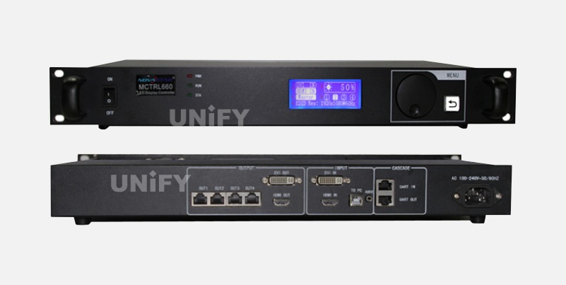
Figure 2-12 MCTRL660 product appearance
(4) From Standalone Controllers to Video Controllers
In the display industry, an LED controller is also known as a pure sending card, standalone master controller, etc.. We mentioned video processors earlier; in fact, a significant function of a video processor is to compensate for the shortcomings of a controller. The reason a controller is also called a pure sending card is that it does not have any video processing functions. For example, when the input source resolution is “1080p” and the LED display’s resolution is 800×600 pixels, the LED display can only show the image content from the top-left 800×600 pixel area of the video source. It cannot perform scaling for display, which is what is often referred to in the display industry as “dot-to-dot display.”
Furthermore, in some application scenarios, a display will have a need for multi-window display. Traditional controller devices cannot meet this need, so a video processor is required to process the video source before providing it to the controller. The addition of a video processor also increases the user’s cost. To solve this problem, control system manufacturers introduced video controller devices (also known as two-in-one controllers). These devices have both the functions of a controller and simple video processing capabilities, such as NovaStar’s V1260 product. The appearance of the V1260 product is shown in Figures 2-13 .
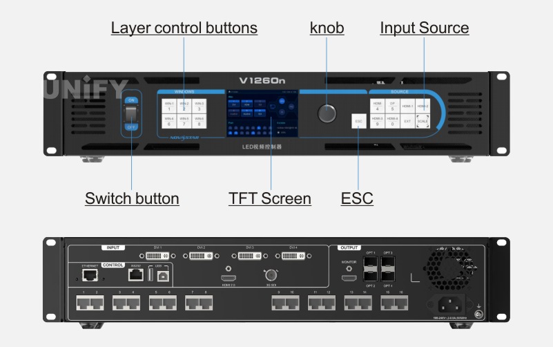
Figure 2-13V1260 product appearance
Common Receiving Card Products in Control Systems
In a control system, the receiving card acts like a central nervous system; it coordinates with the controller to achieve precise control over the millions or even tens of millions of pixels on an LED display.
1. Receiving Card Hardware Introduction
Compared to controller devices, the hardware composition of a receiving card is much simpler, mainly including power interfaces, indicator lights, HUB interfaces, and Gigabit Ethernet ports. NovaStar’s DH7512 receiving card is shown in Figure 2-14.
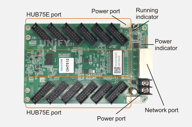
Figure 2-14 NovaStar’s DH7512 receiving card
Power Interface: Provides 5V power to the receiving card.
Gigabit Ethernet Port: Used for signal cascading between the front-end controller device and other receiving cards.
HUB Interface: Common HUB interfaces include HUB75, HUB320, etc.. A ribbon cable is usually used to connect the LED module to the HUB interface for signal control of the module by the receiving card.
Indicator Lights: Indicate the operating status and power supply status of the receiving card.
2. The Development History of Receiving Cards
Like the controllers in the LED control system, receiving cards have also been progressively upgraded, updated, and iterated with the development of the industry and the evolution of the market. The development and evolution of receiving cards have mainly gone through the following stages.
(1) Traditional Large-Sized Receiving Cards
Taking NovaStar’s MRV300 receiving card as an example, it was an early standard receiving card in the industry. The MRV300 receiving card is shown in Figure 2-15. It supports a load capacity of 256×256 pixels and has two 50-pin interfaces for data output. However, since the HUB interface of an LED module is usually a 16-pin HUB75 interface, its definition is inconsistent with the interface on the receiving card, making direct connection via a ribbon cable impossible. Therefore, a HUB adapter board was needed. Thus, early receiving cards usually required a HUB adapter board to be installed first, and then connected to the LED module via a ribbon cable. The HUB adapter board is shown in Figure 2-16.
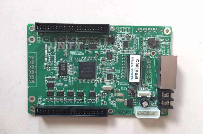
Figure 2-15MRV300 receiving card
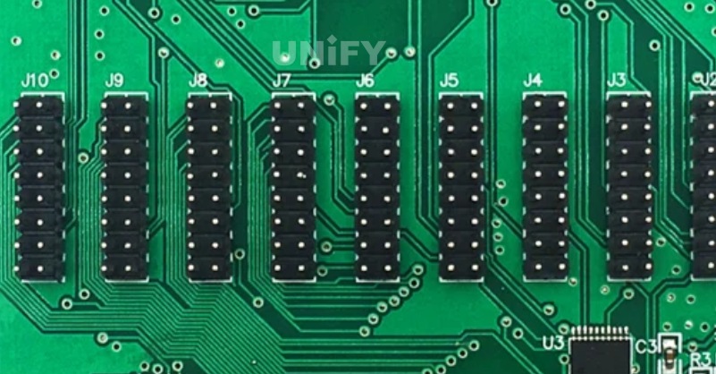
Figure 2-16 HUB adapter board
A receiving card of the same type is Linsn Technology’s RV901T receiving card, as shown in Figure 2-17.
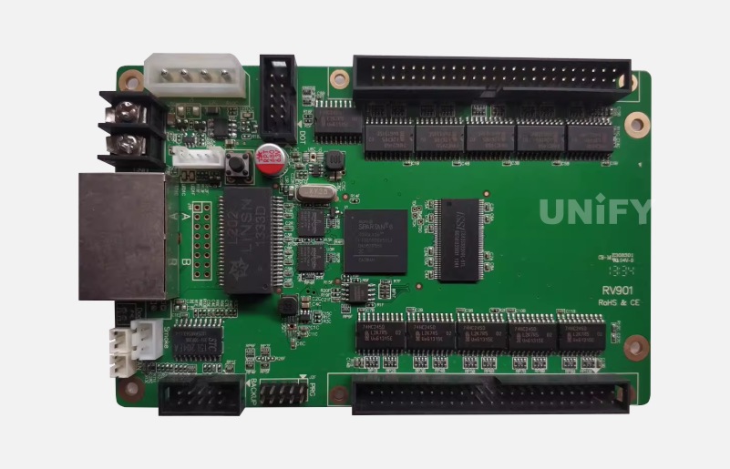
Figure 2-17 Linsn Technology’s RV901T receiving card
(2) HUB-Free Receiving Cards
Early receiving cards needed to be used with specific HUB adapter boards, and over time, the inconvenience of this became more and more prominent. For LED display manufacturers, they needed to match corresponding HUB adapter boards according to their own module designs, and the manufacturing process would be more cumbersome. Control system manufacturers realized that since it was so troublesome, it would be better to simplify things by combining the HUB adapter board and the receiving card into one. This led to the creation of the “HUB-free receiving card” seen in the industry today. Figure2-18shows NovaStar’s DH418 receiving card. It supports a load capacity of 256×256 pixels, and its feature is that it directly integrates the standard HUB75 interface onto the receiving card, allowing the receiving card to be directly connected to an LED module. In addition to the changes in the HUB interface, the power terminals of this type of receiving card were also changed to the same interface as conventional LED modules. These changes fully considered the issues of user deployment, system operation, and maintenance, making deployment easier, system operation more stable, and maintenance more efficient.
A receiving card of the same type is Colorlight’s 5A-75B receiving card, as shown in Figure 2-19.
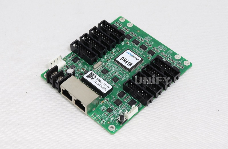
Figure 2-18 NovaStar’s DH418 receiving card
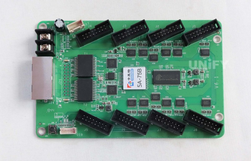
Figure 2-19Colorlight’s 5A-75B receiving card
(3) Small-Sized Receiving Cards
With the development of the display industry, LED displays gradually moved from outdoor application scenarios to indoors, and spread from more engineering fixed installations to rental applications. This required the structure of LED cabinets to be thinner, more convenient, more space-saving, and easier to assemble and install. Many transparent screen designs also required smaller-sized receiving cards.
Cabinet design is naturally constrained by the various components inside the cabinet. To meet market demand, control system manufacturers also needed to design smaller-sized receiving cards. Figure 2-20 shows NovaStar’s MRV210 receiving card. It supports a load capacity of 256×256 pixels and comes with four 26-pin HUB interfaces for connecting to LED modules or cabinet structures, but its size is much smaller than traditional standard receiving cards. This way, in cabinet design, the small-sized receiving card leaves more creative space for LED display manufacturers, meeting the usage needs of displays in more diverse scenarios.
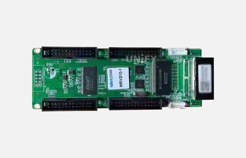
Figure 2-20NovaStar’s MRV210 receiving card
A receiving card of the same type is Linsn Technology’s RV907 receiving card, as shown in Figure 2-21.
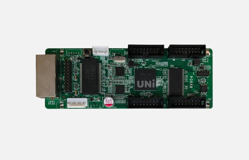
Figure 2-21 Linsn Technology’s RV907 receiving card
(4) DDR2 Interface Receiving Cards
The continuous development of the industry has also consistently driven the pursuit of more new technologies and structural improvements. The MRV210 series of receiving cards saved a lot of space compared to traditional standard receiving cards, but their design with built-in network ports and HUB interfaces made it difficult to further reduce their overall thickness and size. Control system manufacturers began to look for new approaches and technologies. They later discovered that a design similar to the DDR2 interface of computer graphics cards could effectively reduce the physical size of the receiving card. Originally, the receiving card had a network port, but in reality, the LED cabinet also has a network port, so control system manufacturers omitted the network port design on the receiving card. Figure 2-22 shows NovaStar’s XC series of receiving cards. Taking this type of receiving card as an example, the size of the receiving card is reduced. At the same time, the DDR2 interface has good compatibility, and the locking design of the interface is more secure and stable. It can also be designed with dual-card backup, dual-power backup, and cabinet LCD display functions according to scenario needs, which greatly improves the stability factor of the display, thereby ensuring normal display in application scenarios with high-reliability requirements.
Receiving cards of the same type include Brompton Technology’s Tessera R2 and Colorlight’s i9 series receiving cards, as shown in Figures 2-23and 2-24.
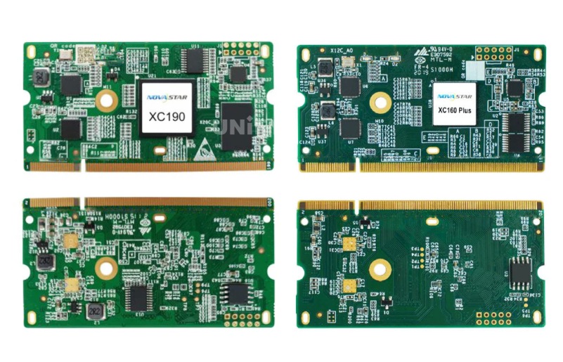
Figure2-22NovaStar’s XC series receiving cards
Figure 2-23Brompton Technology’s Tessera R2 receiving card
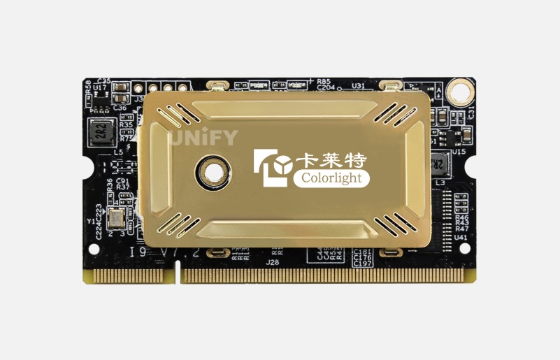
Figure 2-23Colorlight’s i9 receiving card
(5) High-Density Connector Receiving Cards
DDR2 interface receiving cards have their advantages and disadvantages. For example, the commonly used connectors are mostly made of plastic material. LED displays generate a lot of heat when working, and the thermal expansion and contraction of the connectors can lead to poor contact, loose interfaces, and poor dust-proof performance, causing the LED display to work unstably.
Later, a structural design with high-density connectors appeared. NovaStar’s “Axs series” of receiving cards were the first to introduce this interface into the design of receiving cards, as shown in Figure 2-24. This type of interface is dust-proof, anti-loosening, has higher stability, and is compact, only about 70% of the size of a standard bank card. At the same time, this type of receiving card integrates a network transformer, making signal transmission more stable and also simplifying the HUB design for LED display manufacturers.
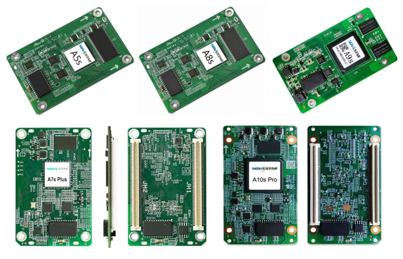
Figure 2-24 NovaStar’s “Axs series” receiving cards
A receiving card with the same high-density connector interface design is Linsn Technology’s Mini913 receiving card, as shown in Figure 2-26.
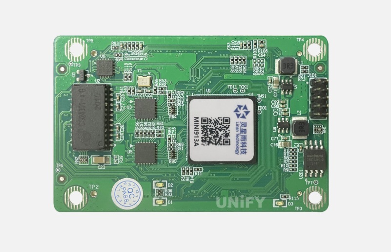
Figure 2-26 Linsn Technology’s Mini913 receiving card
In fact, besides changes in appearance design, the load capacity of receiving cards is also continuously increasing. The early MRV300 receiving card supported a load capacity of 256×256 pixels. Nowadays, the commonly used DH7512 receiving card can already support a load of 512×512 pixels, which is four times the previous capacity. In addition, various control system manufacturers are also developing their own image quality enhancement technologies. The application of these technologies is often inseparable from the cooperation of receiving cards, so the future trend for receiving cards is still to become smaller and smaller in size while becoming more and more powerful in function.
Recommend Products
Indoor LED Screen Case in USA: Elevate Your Church Services
Indoor LED Screen Case in USA: Elevate Your Church Services Home Table of Contents Introduction As churches across the USA seek to engage congregations with richer audio-visual experiences, the adoption of LED display technology has surged. Indoor LED screens are now a central feature in worship spaces, transforming the way messages and media are presented.

Synchronous Playback for LED Displays
Synchronized Playback for LED Displays Home Table of Contents Synchronized Playback for LED Displays After an LED display is configured, it needs to play content from a front-end input. When this content needs to be played in real-time, it is called synchronized playback for an LED display. Synchronized playback refers to the LED display playing
LED Display Basic Calculations
LED Display Basic Calculation Home Table of Contents Power Consumption Calculation In LED display related engineering projects, the power consumption of the screen power supply is a crucial parameter for evaluating screen performance and is closely tied to the safety of project construction. Incorrect calculation of the power consumption of an LED display in the early

Lorem ipsum dolor sit amet, consectetur adipiscing elit. Ut elit tellus, luctus nec ullamcorper mattis, pulvinar dapibus leo.